Seismic stencil codes - part 3#

12 Aug, 2024 by and .
In the last two blog posts, we developed a HIP kernel capable of computing high order finite differences commonly needed in seismic wave propagation. The optimizations enabled the z-direction kernel, the worst performing kernel based on our initial implementation, to achieve both an achieved and effective memory bandwidth close to 1200 GB/s[1] on a single GCD of a MI250X. This performance corresponds to 85 % of the achievable memory bandwidth, see [2]. In this third and final part of the seismic stencil blog series, we optimize the x-direction and y-direction kernels to boost their performances as well. Afterwards, we fuse all three kernels into a single monolithic kernel following the one-pass approach briefly mentioned in the first part of this blog series.
Recall from Part 1 the baseline implementation:
  template <int R>
  __launch_bounds__((BLOCK_DIM_X) * (BLOCK_DIM_Y) * (BLOCK_DIM_Z))
  __global__ void compute_fd_x_kernel(float *__restrict__ p_out, const float *__restrict__ p_in,
          int line, int slice, int x0, int x1, int y0, int y1, int z0, int z1) {

      const int i = x0 + threadIdx.x + blockIdx.x * blockDim.x;
      const int j = y0 + threadIdx.y + blockIdx.y * blockDim.y;
      const int k = z0 + threadIdx.z + blockIdx.z * blockDim.z;

      if (i >= x1 || j >= y1 || k >= z1) return;

      size_t pos = i + line * j + slice * k;
      int stride = 1; // x-direction

      // Shift pointers such that that p_in points to the first value in the stencil
      p_in += pos - R * stride;
      p_out += pos;

      // Compute the finite difference approximation
      float out = 0.0f;
      for (int r = 0; r <= 2 * R; ++r)
          out += p_in[r * stride] * d_dx<R>[r]; // x-direction

      // Write the result
      p_out[0] = out;

  }
The amount of memory traffic at the L1, L2 and HBM memory levels (with memory alignment such that the leading dimension x is padded by 64) for a 512 x 512 x 512 problem size is:
Kernel |
L1 |
L2 read |
L2 write |
HBM |
|---|---|---|---|---|
x-direction: Memory |
6979 MB |
604 MB |
537 MB |
1105 MB |
x-direction: Memory / cube ratio |
13.0 |
1.13 |
1.00 |
2.06 |
y-direction: Memory |
5369 MB |
1610 MB |
537 MB |
1080 MB |
y-direction: Memory / cube ratio |
10.0 |
3.00 |
1.00 |
2.01 |
While the HBM and L2 write ratios report levels we expect (i.e., approximately
2 cubes of movement at the HBM level and 1 cube written from L2), the L1
cache access is undesirably high. This excessive data movement through L1 is a potential
reason why both the effective and achieved memory bandwidths both sit under 1 TB/s[1]
despite up to 1.3 to 1.4 TB/s being possible for simple streaming benchmarks. The next two
optimizations explores techniques aimed at reducing this traffic. Again, we perform all experiments
on a 512 x 512 x 512 cube and R=4 on a single MI250X GCD. Memory alignment and offsets are
enforced such that the leading dimension x is divisible by 64.
Optimization 1 - vectorized floats#
In our finite difference Laplacian series (see here), we introduced the idea of loop unrolling which widens the tile size and increases data reuse through registers. We shall apply something similar here by leveraging vectorized floats. The idea behind this technique is to widen the tile size in the x-direction via vector instructions. As a result, each thread in a thread block is responsible for computing one, two, or four output elements, depending on the vector size. Naturally, vector instructions increase the register pressure per thread, which may hurt occupancy. However, a benefit of the vector instructions is that they leverage the fact that the hardware is capable of requesting data that is up to 128-bits per lane for global memory load and store instructions. Because the instructions are wider, they reduce the total number of global load/store instructions in the program as well as some of the integer arithmetic associated with calculating address offsets. Provided that the occupancy drops by a factor less than the vector size and that there is no register spillage, this optimization increases the number of memory instructions in flight, which is key to saturating the memory bandwidth.
For this to work in our examples, the leading dimension nx must be a
multiple of the vector sizes 1, 2, or 4 (corresponding to float, float2,
or float4, respectively).
First, we begin by introducing some preprocessor headers:
// Vectorized floats
#ifndef VEC_EXP
#define VEC_EXP 0
#endif
#define VEC_LEN (1 << (VEC_EXP))
using vec = __attribute__((__vector_size__(VEC_LEN * sizeof(float)))) float;
The user will pass in a compiler flag -DVEC_EXP with either 0 (no packed math),
1 (float2), or 2 (float4). The fundamental design of our stencil code is that
the normal float arrays are still be passed into the HIP kernels but within the kernels
we introduce new pointers to recast float * into the newly defined vec.
Next, we introduce some additional preprocessor headers
needed for the x-direction HIP kernels:
// x window stencil
#if VEC_LEN == 1
#define XREG RADIUS
#define XREG_VEC RADIUS
#elif VEC_LEN == 2
#if RADIUS > 2
#define XREG 4
#define XREG_VEC 2
#else
#define XREG 2
#define XREG_VEC 1
#endif
#else
#define XREG VEC_LEN
#define XREG_VEC 1
#endif
#define XREG_OFF (XREG-RADIUS)
The vectorized floats need to process adjacent and aligned values from the input buffer, p_in.
For example, when VEC_LEN == 2 i.e., float2, each thread in the x-direction kernel
computes stencils for 2 grid points. Likewise, when VEC_LEN == 4 i.e., float4, each
thread in the x-direction kernel computes stencils for 4 grid points.
Consider the for loop inside the baseline x-direction kernel:
    // Compute the finite difference approximation
    float out = 0.0f;
    for (int r = 0; r <= 2 * R; ++r) {
        out += p_in[0] * d_dz<R>[r];
        p_in += 1;
    }
This code example needs to be rewritten to accommodate for vectorized load and store instructions:
    const vec *p_in_vec = reinterpret_cast<const vec*>(p_in);
    vec *p_out_vec = reinterpret_cast<vec*>(p_out);
    float x_reg[2 * XREG + VEC_LEN] = {0.0f};
    vec *x_reg_vec = reinterpret_cast<vec*>(x_reg);

    // Read x into registers
    for (int r = 0; r < 2 * XREG_VEC + 1; ++r)
        x_reg_vec[r] = p_in_vec[0 - XREG_VEC + r];

    // Compute the finite difference approximation
    vec out = {0.0f};
    for (int r = 0; r <= 2 * R; ++r) {
        for (int ii = 0; ii < VEC_LEN; ++ii)
            out[ii] += x_reg[XREG_OFF + r + ii] * d_dx<R>[r];
    }
Several code changes have been applied:
Recast all the
float *buffers to the newly defined vectorizedvec *Introduce a register
x_regsimilar to the sliding window concept introduced in the previous post. Thisx_regregister contains 9 elements whenR == 4, VEC_LEN == 1but will contain 10 and 12 elements whenVEC_LEN == 2andVEC_LEN == 4, respectively. Likewise, thex_reg_vecregister contains 9, 5, and 3 elements whenVEC_LEN == 1,VEC_LEN == 2, andVEC_LEN == 4, respectivelySplit the for loop into two. The first loop simply loads the vectorized floats into
x_reg_vecThe second loop is a double nested loop where
x_regandd_dx<R>are shifted to compute the finite difference for each of theVEC_LENgrid points.
Below is a pictorial description of how the above definitions fit into the overall vectorization:

Figure 1: This figure illustrates how vectorized loads and stores affect the number of stencil points computed for a thread. Each thread performs the same operation that requires reading multiple values from data stored in registers and computes the stencil formula for multiple outputs, determined by the vector length, `VEC_LEN`. The arrows pointing into the register array show global load instructions and the arrows pointing away from the register array show global store instructions. This implementation therefore relies on the L1 cache to efficiently re-use many of the requested stencil neighbors.
Another significant change is the kernel launch configuration:
#define BLOCK_DIM_X (64 * (4 / RADIUS))
#define BLOCK_DIM_Y RADIUS
Previously, the stencil kernels were launched with a thread block configuration of 256 x 1.
Now, the thread block configuration is selected based on the order of the finite difference
approximation. So if R=4, then the kernel has a thread block configuration of 64 x 4.
The full code with launch parameters is:
template <int R>
__launch_bounds__((BLOCK_DIM_X) * (BLOCK_DIM_Y))
__global__ void compute_fd_x_vec_kernel(float *__restrict__ p_out, const float *__restrict__ p_in,
        int line, int slice, int x0, int x1, int y0, int y1, int z0, int z1) {

    const int i = x0 + VEC_LEN * (threadIdx.x + blockIdx.x * blockDim.x);
    const int j = y0 + threadIdx.y + blockIdx.y * blockDim.y;
    const int k = z0 + threadIdx.z + blockIdx.z * blockDim.z;

    if (i >= x1 || j >= y1 || k >= z1) return;

    size_t pos = i + line * j + slice * k;

    // Shift pointers such that that p_in points to the first value in the stencil
    p_in += pos;
    p_out += pos;

    const vec *p_in_vec = reinterpret_cast<const vec*>(p_in);
    vec *p_out_vec = reinterpret_cast<vec*>(p_out);
    float x_reg[2 * XREG + VEC_LEN] = {0.0f};
    vec *x_reg_vec = reinterpret_cast<vec*>(x_reg);

    // Read x into registers
    for (int r = 0; r < 2 * XREG_VEC + 1; ++r)
        x_reg_vec[r] = p_in_vec[0 - XREG_VEC + r];

    // Compute the finite difference approximation
    vec out = {0.0f};
    for (int r = 0; r <= 2 * R; ++r) {
        for (int ii = 0; ii < VEC_LEN; ++ii)
            out[ii] += x_reg[XREG_OFF + r + ii] * d_dx<R>[r];
    }

    // Write the result
    p_out_vec[0] = out;

}

template <int R>
void compute_fd_x_vec(float *p_out, const float *p_in, const float *d, int line, int
        slice, int x0, int x1, int y0, int y1, int z0, int z1) {

    dim3 block (BLOCK_DIM_X, BLOCK_DIM_Y);
    dim3 grid;
    grid.x = ceil(x1 - x0, VEC_LEN * block.x);
    grid.y = ceil(y1 - y0, block.y);
    grid.z = ceil(z1 - z0, block.z);

    compute_fd_x_vec_kernel<R><<<grid, block>>>(p_out, p_in, d, line, slice, x0, x1, y0, y1, z0,
            z1);
    HIP_CHECK(hipGetLastError());

}
The code transformation to vectorize the y-direction kernel is simpler:
template <int R>
__launch_bounds__((BLOCK_DIM_X) * (BLOCK_DIM_Y))
__global__ void compute_fd_y_vec_kernel(float *__restrict__ p_out, const float *__restrict__ p_in,
        int line, int slice, int x0, int x1, int y0, int y1, int z0, int z1) {

    const int i = x0 + VEC_LEN * (threadIdx.x + blockIdx.x * blockDim.x);
    const int j = y0 + threadIdx.y + blockIdx.y * blockDim.y;
    const int k = z0 + threadIdx.z + blockIdx.z * blockDim.z;

    if (i >= x1 || j >= y1 || k >= z1) return;

    size_t pos = i + line * j + slice * k;
    size_t line_vec = line >> VEC_EXP;

    // Shift pointers such that that p_in points to the first value in the stencil
    p_in += pos - R * line;
    p_out += pos;

    const vec *p_in_vec = reinterpret_cast<const vec*>(p_in);
    vec *p_out_vec = reinterpret_cast<vec*>(p_out);

    // Compute the finite difference approximation
    vec out = {0.0f};
    for (int r = 0; r <= 2 * R; ++r) {
        out += p_in_vec[0] * d_dy<R>[r];
        p_in_vec += line_vec;
    }

    // Write the result
    p_out_vec[0] = out;
}
Similar to the x-direction kernel, each thread outputs VEC_LEN elements in the x-direction
However, when accessing the data to load, it is being loaded from a vectorized type while striding
in the y-direction. Therefore, the stride needs to be modified based on
the vector length, VEC_LEN. This kernel uses the same thread block configuration as before.
Below are the memory bandwidth numbers:
Kernel |
Effective memory bandwidth |
Achieved memory bandwidth |
|---|---|---|
x-direction: Baseline |
990 GB/s |
1018 GB/s |
x-direction: |
980 GB/s |
1007 GB/s |
x-direction: |
1216 GB/s |
1256 GB/s |
x-direction: |
1240 GB/s |
1280 GB/s |
y-direction: Baseline |
966 GB/s |
970 GB/s |
y-direction: |
967 GB/s |
968 GB/s |
y-direction: |
831 GB/s |
834 GB/s |
y-direction: |
1163 GB/s |
1172 GB/s |
A few observations here. First, the baseline and VEC_LEN=1 kernels
perform similarly which is expected since both operate on float arrays.
Secondly, all the kernels benefit from packed FP32 operations.
When VEC_LEN=2, both the effective and achieved memory bandwidths
are very high for the x-direction kernel. The y-direction kernel has
some mixed results depending on the VEC_LEN, but when VEC_LEN=4,
the kernel also performs well. Let us now dive a little deeper into
the memory level traffic:
Kernel |
L1 |
L2 read |
L2 write |
HBM |
|---|---|---|---|---|
x-direction: Baseline |
6979 MB |
604 MB |
537 MB |
1105 MB |
x-direction: |
6979 MB |
805 MB |
537 MB |
1105 MB |
x-direction: |
5906 MB |
672 MB |
537 MB |
1105 MB |
x-direction: |
3221 MB |
604 MB |
537 MB |
1105 MB |
y-direction: Baseline |
5369 MB |
1610 MB |
537 MB |
1080 MB |
y-direction: |
5369 MB |
1610 MB |
537 MB |
1080 MB |
y-direction: |
10737 MB |
1611 MB |
537 MB |
1080 MB |
y-direction: |
5369 MB |
1758 MB |
537 MB |
1080 MB |
For the x-direction kernels, packing the FP32 operations and data movement
reduces the amount of L1 traffic. In the case where VEC_LEN=2, the L1 traffic
nearly doubled, suggesting that there is a lack of coalescing. The y-direction kernel,
even with VEC_LEN=4, is slightly behind the corresponding x-direction kernel, but experiences high levels of L1 traffic.
Let us now consider a second optimization targeting the y-direction.
Kernel fusion#
Now that all three directional kernels are highly optimized, the next task is to combine them into a single kernel to further reduce data movement. One of the challenges with applying kernel fusion is that it often stresses the available hardware resources like registers and LDS. As a result, it may be necessary to reduce the tile size and or occupancy. In this case, we will see that we can maintain the same tile size as before. First, by applying vectorization and LDS, we combine the x-direction and y-direction kernels:
template <int R>
__launch_bounds__((BLOCK_DIM_X) * (BLOCK_DIM_Y))
__global__ void compute_fd_xy_lds_vec_kernel(float *p_out, const float *p_in, const float *d, int line, int
        slice, int x0, int x1, int y0, int y1, int z0, int z1) {

    const int sj = y0 + threadIdx.y;
    const int lds_y = BLOCK_DIM_Y + 2*R;
    const int i = x0 + VEC_LEN*(threadIdx.x + blockIdx.x * blockDim.x);
    const int j = sj + blockIdx.y * blockDim.y;
    const int k = z0 + threadIdx.z + blockIdx.z * blockDim.z;
    size_t pos = i + line * j + slice * k;
    size_t spos = threadIdx.x + sj * BLOCK_DIM_X;
    size_t line_vec = line >> VEC_EXP;

    p_in += pos;
    p_out += pos;
    float x_reg[2 * XREG + VEC_LEN] = {0.0f};
    __shared__ vec smem[BLOCK_DIM_X * lds_y];

    // Recast as vectorized floats
    const vec *p_in_vec = reinterpret_cast<const vec*>(p_in);
    vec *p_out_vec = reinterpret_cast<vec*>(p_out);
    vec *x_reg_vec = reinterpret_cast<vec*>(x_reg);

    // Read x into registers
    for (int r = 0; r < 2*XREG_VEC+1; ++r)
        x_reg_vec[r] = p_in_vec[0 - XREG_VEC + r];

    // Read y into LDS
    smem[spos] = x_reg_vec[XREG_VEC];
    smem[spos - (BLOCK_DIM_X * R)] = p_in_vec[0 - R*line_vec];
    smem[spos + BLOCK_DIM_X * BLOCK_DIM_Y] = p_in_vec[0 + line_vec * BLOCK_DIM_Y];
    __syncthreads();

    if (i >= x1 || j >= y1 || k >= z1) return;

    // Compute the finite difference approximation in the xy-direction
    vec out = {0.0f};
    for (int r = 0; r <= 2 * R; ++r) {
        out += smem[spos + (r - R) * BLOCK_DIM_X] * d_dy<R>[r];
        for (int ii = 0; ii < VEC_LEN; ++ii)
            out[ii] += x_reg[XREG_OFF + r + ii] * d_dx<R>[r];
    }

    __builtin_nontemporal_store(out,&p_out_vec[0]);

}
Also note that we are introducing nontemporal stores via the intrinsic __builtin_nontemporal_store, see
Finite Difference Laplacian Part 3
for more details. Below are the performance numbers in comparison with the single direction kernels:
Kernel |
Effective memory bandwidth |
Achieved memory bandwidth |
|---|---|---|
x-direction: |
1240 GB/s |
1280 GB/s |
y-direction: |
1272 GB/s |
1289 GB/s |
xy-direction: |
1252 GB/s |
1292 GB/s |
The xy-direction kernel itself is comparable to the x-direction and y-direction kernels. One can expect up to a 2x in savings in data movement from this optimization. The next challenge is to combine this fused kernel with z-direction kernel that uses the sliding window technique.
template <int R>
__launch_bounds__((BLOCK_DIM_X) * (BLOCK_DIM_Y))
__global__ void compute_fd_xyz_lds_window_vec_kernel(float *p_out, const float *p_in, int line, int
        slice, int x0, int x1, int y0, int y1, int z0, int z1, int nw) {

    const size_t i = (x0 + VEC_LEN * (threadIdx.x + blockIdx.x * blockDim.x));
    const size_t j = y0 + threadIdx.y + blockIdx.y * blockDim.y;

    if (i >= x1) return;

    // Determine the k indices covered by this sliding window
    // The extent cannot exceed the z1
    const int kbegin = z0 + blockIdx.z * nw;
    const int kend = kbegin + nw > z1 ? z1 : kbegin + nw;

    size_t pos = i + line * j + slice * kbegin;
    size_t slice_vec = slice >> VEC_EXP;
    size_t line_vec = line >> VEC_EXP;

    // Shift pointers such that that p_in points to the first value in the sliding window
    p_in += pos - R * slice;
    p_out += pos;
    const vec *p_in_vec = reinterpret_cast<const vec*>(p_in);
    vec *p_out_vec = reinterpret_cast<vec*>(p_out);

     // LDS for y direction
    const int lds_y = BLOCK_DIM_Y + 2*R;
    const int sj = y0 + threadIdx.y;
    size_t spos = threadIdx.x + sj * BLOCK_DIM_X;
    __shared__ vec smem[BLOCK_DIM_X * lds_y];

    // z direction sliding window
    vec w[2 * R + 1];

    // solution register
    vec out[R+1];

    // x direction stencil
    float x_reg[2 * XREG + VEC_LEN];
    vec *x_reg_vec = reinterpret_cast<vec*>(x_reg);

    // 1. Prime the z sliding window
    for (int r = 0; r < R; ++r) {
        w[r] = p_in_vec[0];
        p_in_vec += slice_vec;
    }
    for (int r = R; r < 2 * R; ++r) {

        // 2. Load x into registers
        for (int r2 = 0; r2 < 2*XREG_VEC + 1; ++r2)
            x_reg_vec[r2] = p_in_vec[0 - XREG_VEC + r2];

        // 3. Load y into LDS
        __syncthreads();
        {
            smem[spos - (BLOCK_DIM_X * R)] = p_in_vec[0 - R * line_vec];
            smem[spos] = x_reg_vec[XREG_VEC];
            smem[spos + (BLOCK_DIM_X * BLOCK_DIM_Y)] = p_in_vec[0 + line_vec * BLOCK_DIM_Y];
        }
        __syncthreads();

        // 4. Compute xy stencils
        out[r-R] = {0.0f};
        for (int r2 = 0; r2 <= 2 * R; ++r2) {
            out[r-R] += smem[spos + (r2 - R) * BLOCK_DIM_X] * d_dy<R>[r2]; // y-direction
            for (int ii = 0; ii < VEC_LEN; ++ii)
                out[r-R][ii] += x_reg[XREG_OFF + r2 + ii] * d_dx<R>[r2]; // x-direction
        }

        // Prime the z sliding window
        w[r] = x_reg_vec[XREG_VEC];
        p_in_vec += slice_vec;
    }

    // Apply the sliding window along the given grid direction
    for (int k = kbegin; k < kend; ++k) {

        // 2. Load x into registers
        for (int r2 = 0; r2 < 2*XREG_VEC+1; ++r2)
            x_reg_vec[r2] = p_in_vec[0 - XREG_VEC + r2]; // x - R

        // 3. Load y into LDS
        __syncthreads();
        {
            smem[spos - (BLOCK_DIM_X * R)] = p_in_vec[0 - R * line_vec]; // y - R
            smem[spos] = x_reg_vec[XREG_VEC];
            smem[spos + (BLOCK_DIM_X * BLOCK_DIM_Y)] = p_in_vec[0 + line_vec * BLOCK_DIM_Y]; // y + R
        }
        __syncthreads();

        // 4. Compute xyz stencils
        w[2*R] = x_reg_vec[XREG_VEC];
        out[R] = {0.0f};
        for (int r = 0; r <= 2 * R; ++r) {
            out[0] += w[r] * d_dz<R>[r]; // z-direction
            out[R] += smem[spos + (r - R) * BLOCK_DIM_X] * d_dy<R>[r]; // y-direction
            for (int ii = 0; ii < VEC_LEN; ++ii)
                out[R][ii] += x_reg[XREG_OFF + r + ii] * d_dx<R>[r]; // x-direction
        }

        // 5. Write only if within y boundary
        if (j < y1)
            __builtin_nontemporal_store(out[0],&p_out_vec[0]);

        // 6. Update the sliding window by shifting it forward one step
        for (int r = 0; r < R; ++r)
            out[r] = out[r+1];
        for (int r = 0; r < 2*R; ++r)
            w[r] = w[r+1];

        // Increment pointers
        p_in_vec += slice_vec;
        p_out_vec += slice_vec;
    }
}
For this final monolithic kernel, we summarize few key ingredients below.
Exit if the threads exceeds
x1onlySplit the priming step into two parts
First part loads the z-direction stencil into a sliding window register
wSecond part still loads the z-direction stencil but also computes the x and y direction stencils and stores the result into a temporary output register
outDuring the sliding window phase, the z-direction stencil computes and combines with the previously store xy-direction stencil.
Introduce additional
__syncthreads()before the LDS load operations to avoid any data hazardsWrite the result only if the thread does not exceed
y1
Below is the result across various values of nw:
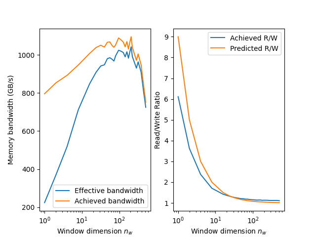
Figure 1: The fully combined xyz kernel reach over 1000 GB/s in both the achieved and effective memory bandwidths. The R/W ratio drops and approaches one as the window size increases.
At around nw = 100 and nw = 200, both memory bandwidth FOMs hit just over 1000 GB/s.
It should also be noted that as nw increases, the R/W hovers slightly above 1 and
is worse than the predicted value calculated from Part 2.
Another interesting observation, unlike in the z-direction sliding window kernel, is that
both the achieved and memory bandwidths are relatively lower when nw is either too
small or too large.
Even the optimal range of numbers still fall short of the 1200 GB/s observed from the individual directional kernels. However, executing the fused xyz-kernel is still faster than executing the three individual optimized kernels or the xy-direction and z-direction sliding window kernels sequentially.
We can approximate the speedup with these formulas:
Where \(T\) represents the kernel execution time and \(N\) represents the size of the cube. The speedup one can achieve over executing the three individual kernels is approximated using the following formula:
Likewise, if we wished to combine only the xy-direction kernel, the speedup is:
Even with this initial attempt at combining the three kernels into a single pass approach, it still offers up to a 1.63x - 2.42x speedup.
Summary and next steps#
In these last three blog posts, we have covered a basic HIP implementation of computing seismic stencils with high order finite difference computations. Using the same performance metrics as the Finite Difference Laplacian series, we developed a methodology to approximate the effective memory bandwidth and compared it against the achieved or actual memory bandwidth. These posts focused on the following optimization strategies.
Aligned memory: this optimization uses padded memory allocations so that the leading dimension is some multiple of the GPU cache line size.
Sliding window: this technique holds onto a local volume of the input array data in registers and compute the stencil in the z-direction entirely using these registers. This “window” helps eliminate redundant global memory fetches as the kernel iterates through xy-planes
Vectorization: recast our
floatdevice buffers asfloat2orfloat4buffers. This technique increases the number of bytes in flight and reduces the number of global load/store instructionsLocal Data Share (LDS): utilization of the LDS to store the grid data and compute the stencil in the y-direction reduces pressure on global memory (caches and HBM). While storing all the grid data in LDS instead of in registers may help reduce register pressure, allocating too much LDS per thread block lowers the occupancy.
All four optimizations result in significant performance boosts for the individual directional kernels. Furthermore, combining the x and y kernels with the above optimizations gives near identical performance to the x-direction and y-direction kernels. The final optimization fused all three stencil kernels into a single one. The end result is a one-pass approach yielding nearly a 2.5x speedup over the three-pass approach.
In the next blog post, we extend this effort to even higher order finite difference stencils, i.e., beyond R=4,
and study the performance across different grid sizes and hardware architecture. If you have any questions,
please do not hesitate to reach out to us on Github Discussions.