Occupancy Math on the AMD MI355X GPU (CDNA4): A From-First-Principles Guide#

Ask a GPU kernel engineer how their kernel is doing and occupancy comes up within a sentence or two. It’s the number everyone quotes and the dial everyone reaches for — and, in our experience, the metric people understand least. Most treat it as an opaque percentage the profiler hands back. It isn’t. Occupancy is fully derivable by hand from a kernel’s resource usage and a handful of fixed hardware limits, and being able to do that derivation changes how you tune. In short: on MI355X GPU occupancy is set by whichever of four resource limiters runs out first (VGPRs and SGPRs — vector and scalar registers; LDS — the on-chip shared scratchpad; or workgroup/barrier slots), the VGPR file is 512 per lane, shared by regular and accumulator registers (not a separate AccVGPR pool), and maximizing occupancy is usually the wrong goal — in a measured MXFP8 MFMA sweep below, the matrix core holds ~97% of peak even as occupancy falls to a fraction of full.
This is a from-first-principles guide to occupancy math on the AMD Instinct™ MI355X GPU (CDNA4, gfx950). We’ll build it from the silicon up: what the hardware budget actually is, which four resources cap how many wavefronts can go resident, and how to compute a kernel’s occupancy ceiling on paper and then confirm it with rocprofv3. The worked examples lean on MXFP8 GEMM (general matrix-multiply) tiles — the kind of kernel where these numbers decide whether the kernel is fast.
The post is in three parts:
Part 1 — The MI355X GPU Architecture. The CU, the four SIMDs, the wavefront, the Matrix Core, and the memory hierarchy that feeds them — the resources the math counts.
Part 2 — Occupancy Math. The definition, the four limiters (VGPRs, SGPRs, LDS, and workgroup/barrier slots), the per-SIMD vs per-CU split that trips everyone up, worked examples, and how to measure occupancy for real.
Part 3 — Better Performance at Lower Occupancy. The twist at the end: once you can compute the ceiling, why reaching for it is often the wrong move. Little’s Law, ILP versus occupancy, and a microbenchmark where the matrix core stays saturated even as occupancy collapses.
Occupancy is worth understanding precisely — both so you can fix the kernels that are genuinely occupancy-limited, and so you can recognize the ones that aren’t.
Part 1 — The MI355X GPU Architecture#
Occupancy is, start to finish, a story about how a fixed pool of resources gets divided among the work you launch. So before any of the math lands, you need a clear mental model of the chip — and in particular, which resources are private and which are shared. We’ll build it top-down and keep returning to that one distinction, because it’s the hinge the whole calculation turns on. Figure 1 sets the scene with the chip from the top down.
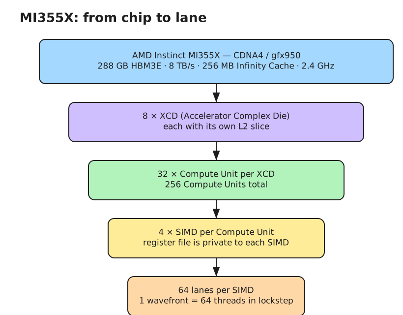
Figure 1: The MI355X GPU (CDNA4) from the top down — 8 XCDs, 256 Compute Units, Infinity Cache, and HBM3E. For occupancy, the only unit that matters is the Compute Unit.#
The Chip, Top Down#
The MI355X GPU is based on the AMD CDNA™4 architecture, ISA target gfx950. At the top level it’s eight Accelerator Complex Dies (XCDs) stitched together over fourth-gen Infinity Fabric, totaling 256 Compute Units — 32 per XCD — clocked up to 2.4 GHz. Wrapped around the dies are 288 GB of HBM3E at 8 TB/s, fronted by 256 MB of last-level Infinity Cache. Each XCD carries its own L2 slice, which is why scheduling that keeps a tile’s traffic on one die (XCD-aware swizzling) pays off — but that’s a locality story, not an occupancy one.
For occupancy, the only unit you reason about is the Compute Unit. Everything above it governs how data moves; occupancy is decided one CU at a time. So that’s where we zoom in.
Inside a Compute Unit#
A CU is four SIMD units (single-instruction, multiple-data — the vector engines that actually run your threads) plus shared infrastructure. Each SIMD is 64 lanes wide and owns a private register file. The pieces that matter:
VGPRs (vector general-purpose registers) — a 512-entry-per-lane vector register file, private to the SIMD. Allocated per wave. This is usually the resource that caps occupancy.
AccVGPRs — the matrix accumulators, carved from that same 512 file. MFMA (matrix fused multiply-add) instructions can accumulate here. On CDNA4 the file is split between regular VGPRs (≤256/wave) and accumulation VGPRs (≤256/wave), but the two share one 512-entry budget — a wave’s regular plus accumulator count is what’s measured against 512 (ISA §3.6.4: “up to 512 total VGPRs, 256 of each type… the number of each type is flexible”). This is not the separate physical ACC file of MI100/MI200; CDNA3 unified them and CDNA4 keeps it that way. In practice the compiler fills regular VGPRs first: most of the MXFP8 GEMM tiles we profiled run with zero AccVGPRs — the accumulator sits in regular VGPRs — and only the largest tiles spill into the accumulator pool. Either way it’s one budget: regular registers and accumulators draw on the same 512 entries.
SGPRs (scalar general-purpose registers) — ~800 per SIMD. Allocated per wave; hold values that are uniform across the wave. Rarely the binding limit.
LDS (Local Data Share) — 160 KB, shared across all four SIMDs. A software-managed on-chip scratchpad, one per CU — NVIDIA calls the equivalent “shared memory.” It’s the cooperation mechanism for a workgroup, and on CDNA4 it’s 2.5× the size of CDNA3’s 64 KB.
Here’s the distinction to burn in: the register files are per-SIMD; the LDS is per-CU. A wave that lands on SIMD 0 cannot touch SIMD 1’s registers, but every wave in a workgroup — wherever it lands — sees the same LDS. That single asymmetry is why the four occupancy limiters don’t share a denominator — the reason the math below needs a unit conversion. Figure 2 lays out the CU and makes that per-SIMD vs. per-CU split explicit.
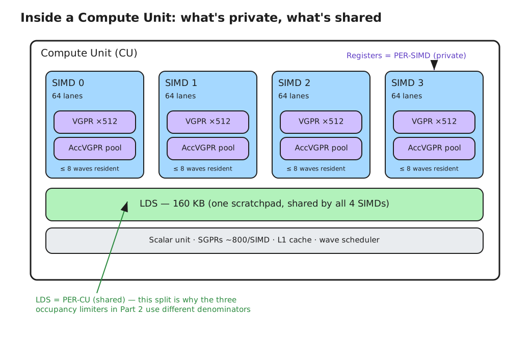
Figure 2: Inside a Compute Unit — four SIMDs, each with a private 512-entry VGPR file, plus the per-CU 160 KB LDS shared across all four. Registers are per-SIMD; LDS is per-CU.#
Threads, Lanes, and Wavefronts#
The hardware doesn’t execute threads one at a time. It executes wavefronts: bundles of 64 threads that run in lockstep on a SIMD’s 64 lanes. The AMD wavefront is 64 threads wide — and “wave” and “wavefront” are the same thing. A 256-thread workgroup is therefore four waves, not 256 independent units of scheduling.
A SIMD holds up to 8 wavefronts resident at once. Resident means their registers are live and reserved; only one wave issues per cycle, and the scheduler hides latency by switching to a different ready wave whenever the current one stalls. Occupancy is just the ratio of resident waves to that maximum of 8 — counted per SIMD, capped at 32 per CU. Crucially, occupancy says nothing about whether those waves are doing useful work; it only counts how many are parked — the distinction the second half of this guide turns on. Figure 3 shows the wavefront execution model that this ratio is built on.
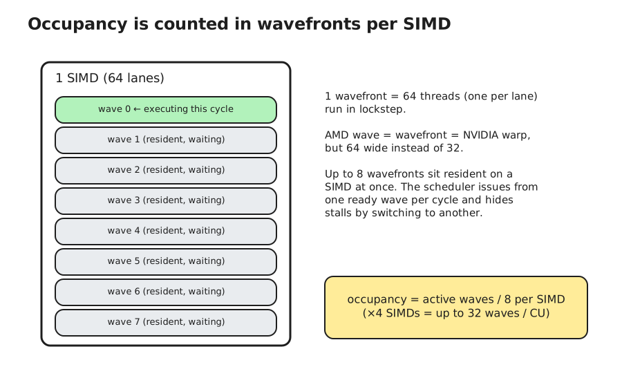
Figure 3: The wavefront model — 64 threads run in lockstep on a SIMD’s 64 lanes; a SIMD holds up to 8 resident waves, and occupancy is the ratio of resident waves to that maximum.#
If You Think in CUDA: A Rosetta Stone#
AMD’s vocabulary maps almost one-to-one onto NVIDIA’s. If your instincts are CUDA-shaped, read this first and the rest of the post translates itself:
AMD (CDNA4) |
NVIDIA |
Notes |
|---|---|---|
Compute Unit (CU) |
SM |
256 on MI355X GPU |
SIMD — 4 per CU |
SM sub-partition — 4 per SM |
64 lanes each |
Wavefront — 64 threads |
Warp — 32 threads |
AMD waves are 2× wide |
VGPR / AccVGPR |
registers |
one shared 512/lane file |
LDS — 160 KB/CU |
shared memory |
per-CU scratchpad |
Matrix Core / |
Tensor Core / |
|
waves resident per SIMD (≤8) |
warps resident per SM |
the occupancy ratio |
workgroup · |
thread block · |
The one place the analogy frays: NVIDIA has no separate “accumulator register” concept — on CDNA4 the AccVGPRs are simply part of the same register file — a subtlety the rest of this guide depends on.
The Matrix Core#
The reason any of this exists on an AI accelerator is the Matrix Core — the MFMA engine. CDNA4 overhauled it with native FP8, FP6, and FP4 support and roughly doubled per-CU matrix throughput versus CDNA3. The MI355X GPU peaks at about 5 PFLOP/s of MXFP8 and 10 PFLOP/s of MXFP6/FP4 dense matrix throughput, with structured sparsity pushing FP4 past 20 PFLOP/s. The instruction you’ll meet in MXFP8 GEMM kernels is a member of the scaled-MFMA family — v_mfma_scale_f32_16x16x128_f8f6f4 or its 32x32x64 sibling, depending on the tile — which folds per-block microscaling directly into the matrix op.
The mechanical detail that connects back to occupancy: MFMA reads its operands from the VGPR file and accumulates back into registers (regular or accumulator VGPRs — the same 512-entry file). The matrix engine is fed by registers — nothing slower can keep it busy at peak. That’s exactly the tension the memory hierarchy makes concrete.
The Memory Hierarchy#
From fastest and smallest to slowest and largest: the register file (VGPR/AccVGPR, per-SIMD) → LDS (160 KB/CU) → L1 → L2 (per XCD) → 256 MB Infinity Cache → 288 GB of HBM3E at 8 TB/s. Each step down trades bandwidth for capacity.
The gap that matters is the very first one. Only the register file delivers operands fast enough to sustain the Matrix Core at peak; LDS, despite being on-chip and despite CDNA4’s generous 160 KB, is meaningfully slower and prone to bank conflicts. Keeping the hot accumulation register-resident — not in LDS — is what lets a kernel hit the matrix peak. Figure 4 shows the full hierarchy and where that first gap sits.
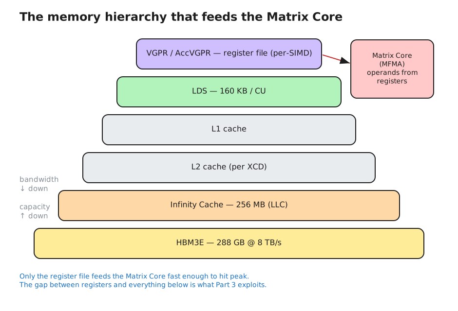
Figure 4: The memory hierarchy, fastest to slowest — register file → LDS → L1 → L2 → Infinity Cache → HBM3E. Only the register file feeds the Matrix Core at peak.#
CDNA3 → CDNA4, in One Box#
What actually changed for kernel authors moving from MI300X/MI325X to MI355X GPU:
LDS: 64 KB → 160 KB per CU. The single biggest occupancy-relevant change; LDS-bound tiles get dramatically more headroom.
Matrix Core: ~2× per-CU throughput, plus native FP6/FP4 (FP6 runs at FP4 rates).
VGPRs: unchanged at 512/SIMD. Despite a common assumption, CDNA4 did not double the vector register file. If you’ve heard otherwise, that’s the myth to drop before doing the math.
With the resources and their boundaries in hand, we can count them.
Part 2 — Occupancy Math#
Occupancy has a one-line definition: it’s the number of wavefronts resident on a SIMD divided by the maximum that SIMD can hold (8). Report it per SIMD or scale it to the CU (max 32 waves) — same ratio either way. The number you get is set by whichever resource runs out first, and there are four candidates.
The Limiters#
Each limiter has the same shape — a fixed hardware budget divided by what one unit of your kernel consumes, floored to a whole number — but they count different things:
VGPRs hold every per-thread value live at once — loaded operands, loop variables, and the accumulator tile — with regular and accumulator registers drawing on one 512-entry file. Bigger tiles and deeper unrolling cost more.
SGPRs hold values uniform across a wave — base addresses, loop bounds, predicates. Usually cheap.
LDS holds the workgroup’s shared staging buffers: the tiles you cooperatively load before feeding the matrix core.
Workgroup slots and barriers are spent once per resident workgroup, no matter how large or small it is.
As formulas:
VGPR limit:  floor( 512 / total-VGPRs-per-lane  )  ->  waves / SIMD   (total = regular + accumulator)
SGPR limit:  floor( ~800   / SGPRs-per-wave     )  ->  waves / SIMD
LDS  limit:  floor( 160 KB / LDS-per-workgroup  )  ->  workgroups / CU
WG   limit:  max workgroups resident / CU          (hard cap + barrier slots)
Your occupancy is the minimum of the four, then clamped by the hardware caps (8 waves/SIMD, 32 waves/CU). In practice VGPRs or LDS bind; SGPRs almost never do unless you have heavy scalar address math.
The fourth limiter is workgroup-level. A CU can hold only a fixed number of resident workgroups, enforced in part by barrier resources — every workgroup of more than one wavefront needs a hardware barrier to implement __syncthreads / s_barrier, and a CU has a limited pool of them. This one stays invisible until your workgroups get small: a swarm of tiny one- or two-wave workgroups can exhaust the workgroup or barrier slots while VGPRs, SGPRs, and LDS still have room to spare. With the 256-thread (4-wave) tiles typical of these GEMM kernels it rarely binds — but for fine-grained kernels it’s the limiter people forget, right up until the profiler shows occupancy stuck below what the register and LDS math predicts. Figure 5 collects all four limiters in one view.
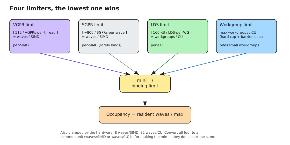
Figure 5: The four occupancy limiters — VGPRs, SGPRs, LDS, and workgroup/barrier slots. Each is a fixed budget divided by per-kernel cost; occupancy is the minimum.#
The Unit Mismatch That Trips Everyone Up#
Notice the limiters don’t all produce the same quantity. VGPRs and SGPRs are per-SIMD resources, so they yield waves per SIMD. LDS is a per-CU resource — one scratchpad shared by all four SIMDs — so it yields workgroups per CU. You can’t take a min across different units; you have to convert first.
The bridge is the workgroup’s wave count and how those waves land on SIMDs. A 256-thread workgroup is 4 waves, and the hardware spreads those 4 waves one-per-SIMD across the CU. So each resident workgroup contributes one wave to every SIMD, which lets you restate the LDS limit (workgroups/CU) in the same waves/SIMD currency as the register limits — and then take the minimum. Larger workgroups change the conversion factor: an 8-wave (512-thread) workgroup puts 2 waves on each SIMD, so each workgroup costs two waves/SIMD instead of one.
Concretely: suppose LDS allows 6 resident workgroups per CU and each workgroup is 4 waves. Those 4 waves spread one-per-SIMD, so 6 workgroups put 6 waves on every SIMD — under the cap of 8, so the LDS limit expressed in waves/SIMD is 6. Only now can you line it up against the VGPR limit (also in waves/SIMD) and take the smaller. Compare a raw 6 workgroups/CU against a 5-wave/SIMD register limit directly and you’re comparing apples to oranges.
A Worked Example#
Take a real MXFP8 GEMM tile — these numbers come straight from a compiled _mxfp8_mm_kernel code object (llvm-objdump --mcpu=gfx950, no spills): a 256-thread workgroup (4 waves) using 128 total VGPRs per lane (all regular — agpr_count is 0, so the accumulator sits in regular VGPRs), 50 SGPRs per wave, and 32 KB of LDS per workgroup. It lowers to v_mfma_scale_f32_32x32x64_f8f6f4, the scaled MXFP8 matrix op. Run the limiters:
VGPR:  floor(512 / 128) = 4 waves / SIMD     (128 = regular + accumulator; agpr_count = 0)
SGPR:  floor(800 / 50)  = 16 waves / SIMD    (not binding)
WG:    workgroup / barrier cap on workgroups/CU   (not binding for a 4-wave tile)
LDS:   depends on the LDS budget, which is exactly what changed across generations
So compare the two generations directly:
CDNA3 (MI300X, 64 KB LDS)
  LDS:  floor(64 / 32) = 2 workgroups/CU  ->  2 waves/SIMD
  min( VGPR 4, SGPR 16, LDS 2 ) = 2 waves/SIMD
  occupancy = 2 / 8 = 25%        <- LDS-bound

CDNA4 (MI355X GPU, 160 KB LDS)
  LDS:  floor(160 / 32) = 5 workgroups/CU  ->  5 waves/SIMD
  min( VGPR 4, SGPR 16, LDS 5 ) = 4 waves/SIMD
  occupancy = 4 / 8 = 50%        <- register-bound
Same kernel, same tile — 25% on CDNA3, 50% on CDNA4. And notice what changed: on MI300X the kernel was strangled by LDS; the 160 KB scratchpad on MI355X GPU lifts that ceiling until the VGPR file (4 waves) becomes the constraint instead. More LDS didn’t just raise the number — it relocated the bottleneck from the shared scratchpad to the per-lane register file. That relocation — not just the higher number — is what hand-computing the limiters shows you and a bare profiler percentage hides. And it keeps moving: heavier variants of this very kernel compile to 202, 294, even 498 total VGPRs — the 294-and-up tiles start spending real AccVGPRs on top of the regular ones, and occupancy slides to 2, then 1 wave/SIMD. Whether sliding down that far is a good trade is what the microbenchmark near the end of this guide measures. Figure 6 puts the two generations of this worked example side by side.
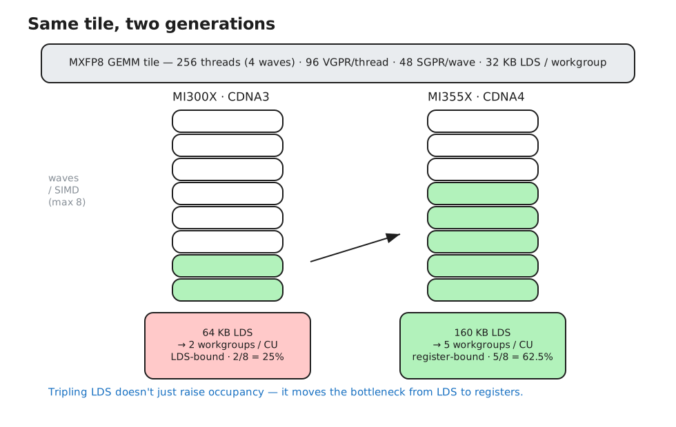
Figure 6: The worked MXFP8 GEMM tile across generations — the same kernel is LDS-bound at 25% on CDNA3 (64 KB LDS) and register-bound at 50% on CDNA4 (160 KB LDS).#
Granularity: Where Hand-Math Drifts from Reality#
The floor divisions above assume your kernel uses exactly the registers you think it does. It doesn’t — the hardware allocates registers in fixed-size blocks, so your effective count is always rounded up to the next block boundary. On CDNA4, VGPRs round up to groups of 8 (ISA §3.6.4: gfx950 allocates the vector file in eight-Dword groups — confirm in your objdump), SGPRs to 16, and LDS to its own block size too.
That rounding can cost a whole wave. Suppose the compiler reports 100 total VGPRs per lane. By hand you’d expect floor(512 / 100) = 5 waves/SIMD, or 62.5%. But with a granularity of 8, 100 rounds up to 104, and floor(512 / 104) = 4 waves — 50%. You silently lost a wave to four registers you didn’t know you were spending.
The flip side is free occupancy. Trim that same kernel back under the boundary — to 96 total VGPRs — and floor(512 / 96) = 5 waves returns you to 62.5%. Shaving a handful of registers to drop below a granularity boundary is one of the cheapest occupancy wins there is, and it’s exactly why you read the rounded number out of the binary rather than trusting the one in your head. When hand math and the profiler disagree by a single wave, granularity is almost always the reason.
Try It: The Occupancy Calculator#
You don’t have to trust the arithmetic — run it. Plug in what the binary reports and watch the binding limiter (and the granularity-8 rounding) decide the answer. It’s preloaded with the worked example above; change a number and see what moves.
occupancy calculator · gfx950
512 VGPR/lane · ~800 SGPR/SIMD · 160 KB LDS/CU · max 8 waves/SIMD · VGPR granularity 8, SGPR 16.
How to Measure It#
Two ways, and you want both. Statically, ask the compiler and the binary what the kernel actually consumes:
# resource usage at compile time
hipcc -Rpass-analysis=kernel-resource-usage kernel.cpp

# or read it straight out of the code object
llvm-objdump --disassemble --mcpu=gfx950 kernel.hsaco | grep -iE "vgpr_count|agpr_count|sgpr_count|group_segment|accum_offset"
roc-obj-ls a.out
Here’s that grep on two real tiles of the MXFP8 GEMM kernel — the small one from the worked example and a much bigger one — with the 512-file split visible in the directives:
# small tile (the worked example): accumulator lives in regular VGPRs
.vgpr_count:          128    # total VGPRs/lane (regular + accumulator)
.agpr_count:          0      #   -> floor(512 / 128) = 4 waves/SIMD
.amdhsa_accum_offset  128    # AccVGPRs would start at 128 -> none used
.sgpr_count:          50
.vgpr_spill_count:    0      # no spills

# big tile: one 512 file, now split across both pools
.vgpr_count:          498    # 252 regular + 246 accumulator = 498 (<= 512)
.agpr_count:          246    #   -> floor(512 / 498) = 1 wave/SIMD
.amdhsa_accum_offset  252    # regular 0..251, AccVGPRs 252..497
Same kernel, two tiles: the small one keeps the accumulator in regular VGPRs (agpr_count 0); the big one spends 246 AccVGPRs — and because both pools draw on the one 512-entry file, vgpr_count already includes them, so the bigger tile’s ceiling collapses to a single wave/SIMD. That’s the shared-512-file point from earlier, visible directly in the binary.
Those give you the inputs to the formulas above — the theoretical occupancy ceiling. For what the kernel achieved at runtime, read OccupancyPercent (or MeanOccupancyPerCU) with rocprofv3, alongside MfmaUtil (matrix-engine busy) and VALUBusy so you can tell whether occupancy is even your problem.
Theory vs. the Profiler#
One caveat sets up everything that follows. The number you derive by hand is a ceiling — the most waves that could be resident given resources. The number rocprofv3 reports is an average over time, and it can land above or below your hand figure for entirely mundane reasons: granularity rounding, partial final workgroups, waves draining at the kernel’s edges, the sampling window. It’s common to derive a 62.5% ceiling and watch the profiler report something a few points off. Neither number is wrong; they answer different questions.
And it raises the question the rest of this guide answers: if occupancy is this slippery to even pin down — and if all it counts is how many waves are parked, not whether they’re doing anything — why treat maximizing it as the goal?
Part 3 — Better Performance at Lower Occupancy#
The previous section ended on a question: if occupancy only counts how many waves are parked, why chase it? The rest of this one answers it.
Occupancy is one mechanism for hiding latency — not the only one. When a wave stalls on a memory load or a long MFMA, the scheduler covers the gap by issuing from another resident wave. More resident waves means more stalls you can paper over. That’s thread-level parallelism (TLP), and it’s real. But it isn’t the only parallelism the hardware can exploit, and treating it as the goal blinds you to the other source.
This argument isn’t new — Vasily Volkov made it for NVIDIA’s Fermi in his 2010 GTC talk, Better Performance at Lower Occupancy. CDNA4 changes the hardware, not the logic.
Little’s Law: How Much Parallelism Do You Actually Need?#
The parallelism required to fully hide latency is given by Little’s Law:
parallelism-in-flight = latency × throughput
To keep a functional unit saturated you need enough independent operations in flight to cover its latency at its issue rate. For the matrix core: if an MFMA takes L cycles to retire and the unit accepts a new one every T cycles, you need roughly L/T independent MFMAs in flight at all times. Fall short and the unit idles between dependent ops; meet it and you’re at peak — regardless of how you supplied those independent ops.
That last qualifier is the crux: Little’s Law asks for independent operations in flight, not for waves.
Two Ways to Get It: TLP and ILP#
There are two ways to put L/T independent MFMAs in flight:
TLP (occupancy): many resident waves, each issuing one MFMA. The independence comes from different waves.
ILP: fewer waves, each issuing several independent MFMAs — multiple accumulator tiles advanced in parallel inside one wave. The independence comes from within the wave.
Both satisfy Little’s Law. And here’s the CDNA4-specific tension: the MFMA accumulator — whether the compiler parks it in regular VGPRs or in AccVGPRs — comes out of the same 512-entry register file as your operands (≤256 of each type, flexibly split; on the small tile above it’s 0 AccVGPRs, with the accumulator living in regular VGPRs). So holding several independent accumulator tiles for ILP spends real register budget: it raises the wave’s total VGPR count and therefore pushes occupancy down. That lower occupancy is the intended trade, not a side effect. ILP and occupancy are two ways to spend one 512-register budget to satisfy Little’s Law, and the claim of this section is that spending it on bigger per-wave tiles (ILP) usually beats spending it on more waves (TLP). Figure 7 contrasts the two routes to the same parallelism.
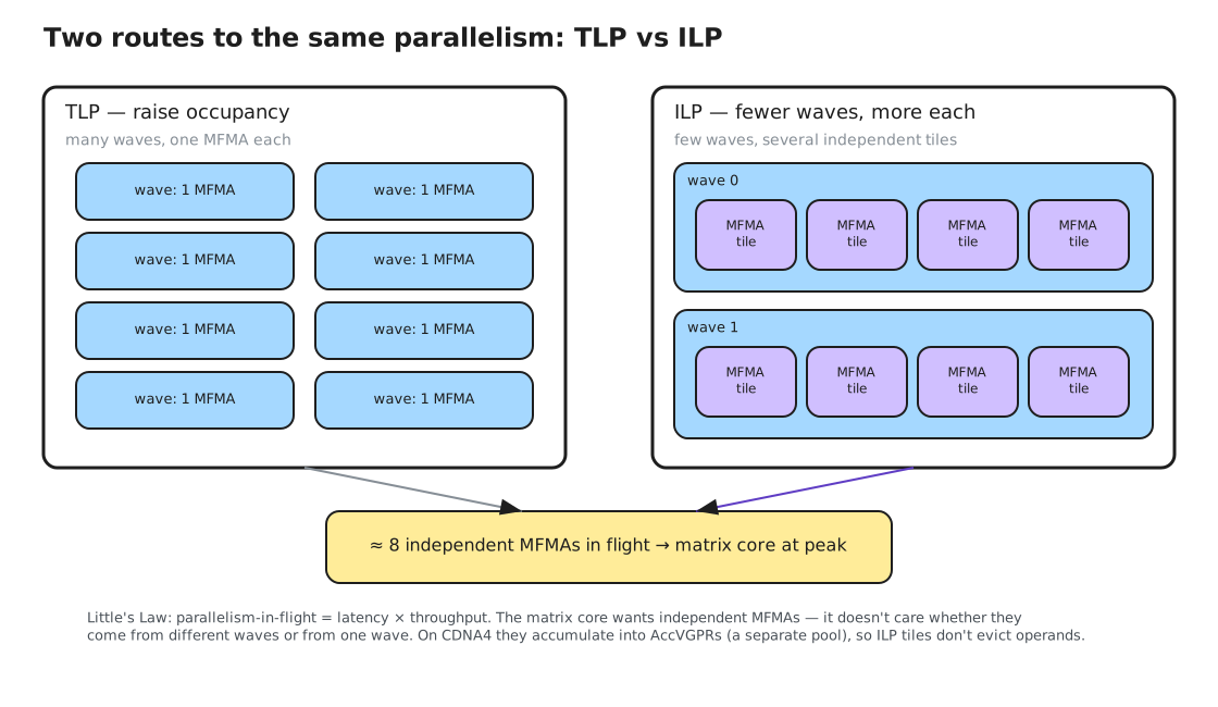
Figure 7: Two ways to satisfy Little’s Law — TLP spreads independent MFMAs across many waves; ILP packs several independent accumulator tiles into one wave. Both draw on the same 512-VGPR file.#
Hiding Arithmetic Latency with Fewer Waves#
You can watch this in isolation, with everything else held still. Take a single MXFP8 matrix instruction — v_mfma_f32_16x16x128_f8f6f4 — and have each wave run K independent accumulator chains in a tight loop. K is the ILP knob: at K=1 every MFMA depends on the one before it (a single chain that exposes the matrix unit’s latency); at K=8 the wave keeps eight independent MFMAs in flight at once. The trick that makes this a clean experiment is throttling occupancy separately — by reserving LDS so only so many waves co-reside per CU — so ILP and occupancy move on independent axes instead of being tangled together the way they are when you simply resize a tile. The whole kernel is about a dozen lines:
typedef float v4f __attribute__((ext_vector_type(4)));
typedef int   v8i __attribute__((ext_vector_type(8)));

template <int ILP>                              // ILP = the parallelism knob
__global__ void __launch_bounds__(256)
mfma_ilp(const v8i* A, const v8i* B, float* out, int iters) {
    extern __shared__ char throttle[];          // reserved LDS = the occupancy dial
    int lane = threadIdx.x & 63;
    v8i a[ILP], b = B[lane];
    v4f acc[ILP];
    #pragma unroll
    for (int i = 0; i < ILP; ++i) {             // distinct A -> chains stay independent
        a[i]   = A[(lane + 7 * i) & 63];
        acc[i] = v4f{0, 0, 0, 0};
    }
    for (int t = 0; t < iters; ++t)
        #pragma unroll
        for (int i = 0; i < ILP; ++i)           // ILP independent MFMAs in flight
            acc[i] = __builtin_amdgcn_mfma_scale_f32_16x16x128_f8f6f4(
                         a[i], b, acc[i], 0, 0, 0, 0, 0, 0);  // MXFP8 scaled MFMA
    float s = 0;                                // sink so the loop isn't optimized away
    #pragma unroll
    for (int i = 0; i < ILP; ++i) s += acc[i][0];
    if (s == -1.f) out[0] = s;
}
// launch:  mfma_ilp<8><<<grid, 256, lds_bytes>>>(A, B, out, iters);
//          raise lds_bytes to walk occupancy down without touching ILP.
Everything that matters is in those two nested loops: ILP independent accumulators (acc[i], each fed by a distinct a[i] so the compiler can’t fuse them), and a separate lds_bytes launch argument that reserves LDS to cap how many waves co-reside. Figure 8 plots throughput in absolute PFLOP/s against achieved occupancy, measured on the MI355X GPU with rocprofv3:
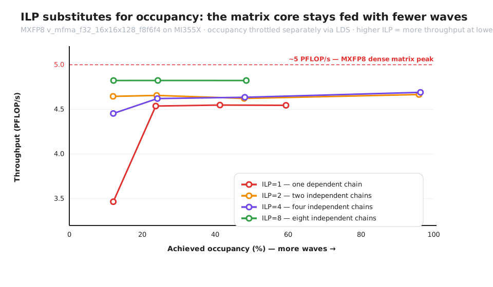
Figure 8: Measured MXFP8 MFMA throughput vs. achieved occupancy on MI355X GPU. ILP=8 holds the ~5 PFLOP/s matrix peak (~4.84 PFLOP/s) flat from ~49% occupancy down to the ~12% one-wave-per-SIMD floor; the single dependent chain (ILP=1) starves to ~3.4 PFLOP/s at that floor and only climbs back as more waves go resident.#
Here is the full sweep — four ILP levels, each walked down in occupancy by reserving LDS:
ILP |
occupancy span |
throughput @ 12% occupancy |
throughput @ max occupancy |
|
|---|---|---|---|---|
1 |
12–59% |
3.47 |
4.55 |
70–95% |
2 |
12–96% |
4.65 |
4.67 |
95–96% |
4 |
12–96% |
4.46 |
4.69 |
90–96% |
8 |
12–49% |
4.82 |
4.83 |
~97% |
The single most telling pair: ILP=8 holds ~4.82 PFLOP/s down to 12% occupancy — more than ILP=2 manages even at 96% occupancy, where it reaches only 4.67. Same chip, same 512-VGPR file, two ways to spend it — on independent accumulator chains (ILP) or on more resident waves (occupancy). The low-occupancy, high-ILP route wins, at one-eighth the occupancy. Maximizing occupancy didn’t just fail to help; the configurations that can reach near-full occupancy (ILP=2 and ILP=4) land below the low-occupancy ILP=8.
Start at the left edge — the lowest occupancy the LDS throttle reaches, ~12%, one workgroup (four waves, one per SIMD) resident per CU. There, ILP=8 already sits at about 4.84 PFLOP/s — ~97% of the MI355X GPU’s ~5 PFLOP/s MXFP8 matrix peak — and it stays flat all the way across the sweep, out to ~49% occupancy: one well-fed wave per SIMD carries enough independent MFMAs to keep the matrix unit saturated, so the extra resident waves more occupancy would buy add nothing. (One honest caveat: that 4.84 is an issue ceiling — the microbench keeps its operands register-resident and moves no memory, so a real HBM-fed GEMM, which must also stream its inputs in, lands lower. What the sweep isolates is the matrix engine itself, and that is emphatically not the resource occupancy was supposed to be protecting.) The single dependent chain (ILP=1), by contrast, starves at that same ~12% floor — only ~3.47 PFLOP/s, because it exposes the matrix unit’s latency and, with one wave per SIMD, has no neighbor to fill the gaps — and it climbs back only as more waves go resident to hide that latency through TLP.
That’s Little’s Law made visible. The matrix core wants a fixed number of independent MFMAs in flight; you can supply them with eight waves of one chain each, or one wave of eight chains — and the second route reaches the same throughput at a fraction of the occupancy. rocprofv3 confirms the mechanism rather than just the outcome: at the ~12% floor, MfmaUtil reads ~70% for ILP=1 but ~98% for ILP=8 — identical wave counts, the matrix engine simply has more independent work to chew on. Both occupancy and matrix utilization track the throughput fraction; there is no regime where the engine is half-busy yet delivering peak FLOPs.
Note
Methodology: MI355X GPU (gfx950), ROCm™ Software 7.0.1; a single HIP kernel where each wave runs K independent v_mfma_f32_16x16x128_f8f6f4 accumulator chains (K = ILP), with occupancy throttled separately by reserving dynamic LDS so a controlled number of 256-thread workgroups co-reside per CU (one workgroup = four waves, one per SIMD; the lowest occupancy this reaches is ~12%). OccupancyPercent and MfmaUtil are rocprofv3 derived metrics read from the kernel dispatch only (normalized to the device’s 32 waves/CU maximum); throughput is a median over repeated launches in absolute PFLOP/s (GMFMA/s × 65,536 ÷ 1e6, where 65,536 = 2·16·16·128 FLOP per 16×16×128 MFMA) — ILP and occupancy are varied on independent axes so neither stands in for the other.
Note
Performance data. Data measured June 6, 2026. Throughput (PFLOP/s) measures the sustained computational performance achieved at different levels of achieved occupancy (%), indicating how efficiently the hardware performs computation as more execution waves are active. All experiments were conducted on 1x AMD MI355X GPU, with ROCm™ Software 7.0.1 installed in the system environment.
System configuration: Model: Supermicro AS-8125GS-TNMR2 · CPU: 2x AMD EPYC™ 9654 96-Core Processor · NUMA: 2 NUMA nodes per socket, NUMA auto-balancing disabled · Memory: 3072 GiB (32 DIMMs x 96 GiB Micron Technology DDR5 4800 MT/s) · Disk: 70 TiB · GPU: 1x AMD MI355X GPU (288 GB) · Host OS: Ubuntu 22.04.4 · System BIOS: 3.2 · System BIOS vendor: American Megatrends International, LLC. · Host GPU driver: ROCm™ 7.0.1.
The same thing in Gluon. The HIP kernel above is the bare-metal version, but the experiment ports cleanly to Gluon — Triton’s new tile-level dialect — where the ILP knob is simply the accumulator width: one mfma_scaled on a 16×(16·ILP) tile emits ILP independent 16×16×128 fragments.
@gluon.jit
def mfma_ilp(out_ptr, iters, ILP: gl.constexpr):
    mfma = gl.amd.AMDMFMALayout(version=4, instr_shape=[16, 16, 128], transposed=True, warps_per_cta=[1, 1])
    dotA = gl.DotOperandLayout(0, mfma, k_width=32)
    dotB = gl.DotOperandLayout(1, mfma, k_width=32)
    a   = gl.full([16, 128],       1, gl.float8e4nv, dotA)   # operands register-resident
    b   = gl.full([128, 16 * ILP], 1, gl.float8e4nv, dotB)
    acc = gl.zeros([16, 16 * ILP], gl.float32, mfma)
    for _ in range(iters):                                   # one call = ILP independent MFMAs
        acc = gl.amd.cdna4.mfma_scaled(a, None, "e4m3", b, None, "e4m3", acc)
    # ... store acc so the loop survives ...
On the same MI355X GPU this reaches 4.97 PFLOP/s — 99% of the MXFP8 matrix peak at full occupancy (a hair above the HIP version, since the Gluon loop carries no per-iteration address arithmetic), and the ILP contrast reproduces: at low wave counts, eight independent chains deliver ~1.8× a single dependent one. Same physics, same ceiling, on AMD’s own tile-level toolchain.
Hiding Memory Latency with Fewer Waves#
The same logic covers memory. Little’s Law for HBM:
bytes-in-flight = HBM latency × bandwidth
At 8 TB/s, even a sub-microsecond HBM latency implies only a few megabytes in flight across the entire 256-CU GPU — on the order of tens of KB per CU. You don’t need 32 waves to reach that; a handful of waves each issuing wide, vectorized buffer_loads, with several loads outstanding before the s_waitcnt, will saturate the bus. The lever is bytes-per-wave-in-flight (vector width × outstanding loads), not wave count. Fetch more per wave and you hide the same latency with fewer of them.
The Register/LDS Bandwidth Gap — and What 160 KB Is Really For#
Recall that only the register file feeds the matrix core at full rate; LDS is slower and bank-conflict-prone. CDNA4’s headline 160 KB of LDS is a real gift, but it’s tempting to misread it as “fast memory you should pack data into.” The accumulator belongs in registers — regular or accumulator VGPRs, the compiler’s choice — never in LDS. That’s the only thing that sustains peak MFMA.
So what is the extra LDS for? Depth. Use it to stage more of the operand stream ahead of the matrix core — deeper software-pipelined prefetch, more buffered K-steps — so the compute units never wait on HBM. The 160 KB buys a longer runway to keep loads ahead of math, which is precisely what lets a low-occupancy, big-tile kernel stay fed. It’s a latency-hiding budget, not an accumulator substitute.
The Roofline Underneath All of This#
Step back and the whole argument is a roofline argument. The MI355X GPU’s machine balance — peak compute over peak bandwidth — is about 5 PFLOP/s ÷ 8 TB/s ≈ 625 FLOP/byte for MXFP8. To live on the flat matrix-core roof rather than the bandwidth slope, a kernel’s arithmetic intensity has to clear that ridge.
Here’s the connection occupancy-chasers miss: arithmetic intensity is set by tile size, not by occupancy. A bigger register-resident output tile reuses each loaded byte across more MFMAs, so its AI climbs with the tile’s footprint — walking the kernel up toward the ridge. Adding waves does nothing good for AI: it splits the same 512-VGPR file into smaller tiles, lowering AI and sliding you back down the bandwidth slope. The two knobs aren’t symmetric — occupancy moves you along the latency-hiding axis; tile size moves you along the roofline. Kernels that win spend the register file on the tile to buy arithmetic intensity, and lean on ILP to hide whatever latency is left.
The Trap: Cranking Occupancy Can Starve the Matrix Core#
This is where the trade bites. The register file is fixed at 512 VGPRs/lane — regular operands and accumulators together — so occupancy and per-wave tile size are in direct, zero-sum tension:
more waves/SIMD  ->  fewer total VGPRs per wave  ->  smaller accumulator tile
                 ->  lower arithmetic intensity (more LDS/HBM traffic per MFMA)
                 ->  matrix core waits on data   ->  throughput DOWN
Past the point where you have just enough waves (plus ILP) to cover latency, every additional wave you buy by shrinking the tile is a wave you didn’t need — paid for with arithmetic intensity you did. That’s how a kernel at 75% occupancy loses to the same kernel reworked to 37.5%: the lower-occupancy version holds a bigger register-resident tile, does more compute per byte moved, and keeps the matrix core saturated through ILP. For MFMA-bound kernels the sweet spot is routinely 2–4 waves/SIMD, not 8. Figure 9 traces that chain of consequences.
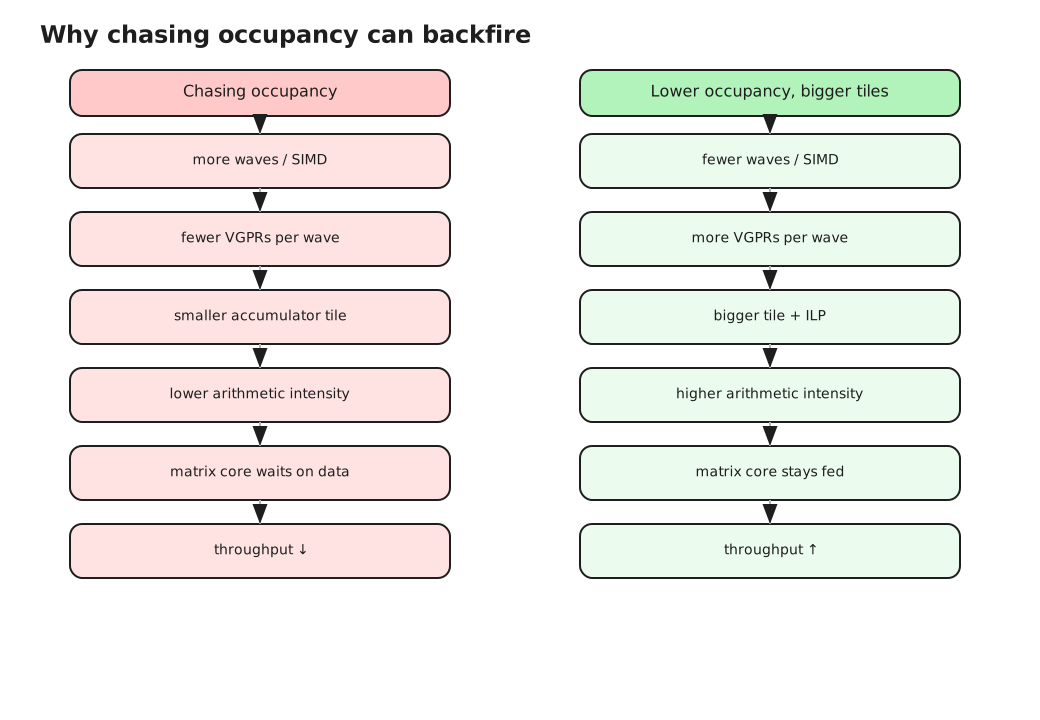
Figure 9: The occupancy trap — buying more waves shrinks the per-wave tile, lowers arithmetic intensity, and starves the matrix core. For MFMA-bound kernels the sweet spot is 2–4 waves/SIMD.#
So What Should You Actually Optimize?#
Not occupancy. Optimize for keeping the matrix core fed: enough parallelism in flight to cover latency, sourced as much from ILP and wide loads as from waves; the biggest register-resident tile that doesn’t spill; LDS spent on pipeline depth, not as an accumulator. Then measure the right thing — matrix-engine and VALU utilization, not the occupancy percentage.
Occupancy is one input to the latency-hiding equation. It was never the answer.
Summary#
We covered the CDNA4 hardware and its private-vs-shared resource split, the four limiters and how to compute occupancy by hand, and why that ceiling is rarely the target. The throughline: occupancy is a diagnostic, not an objective — it tells you how much TLP is resident, which is useful precisely because it lets you reason about whether TLP is what you’re short on.
So here’s how to use all of it. Next time you open a kernel:
Read the real resource usage from the binary (
-Rpass-analysis=kernel-resource-usage,llvm-objdump --mcpu=gfx950) — not the numbers in your head. Mind the granularity rounding.Compute the four limiters, convert them to a common unit, and take the minimum. The minimum is your ceiling; the argmin is your binding resource.
Check whether occupancy is even your problem — pull matrix-engine and VALU utilization from rocprofv3. If the matrix core is already saturated, occupancy is a distraction. Stop here.
If you’re latency-bound, ask where the parallelism should come from. Usually the cheap fix is more ILP (independent accumulator tiles) or wider loads, not more waves.
If you’re matrix-bound and under-fed, spend the register file on the tile, not on waves. Grow the register-resident tile until just before it spills; let occupancy fall; use the 160 KB LDS for pipeline depth.
Figure 10 captures that same workflow as a flowchart you can keep beside the profiler.
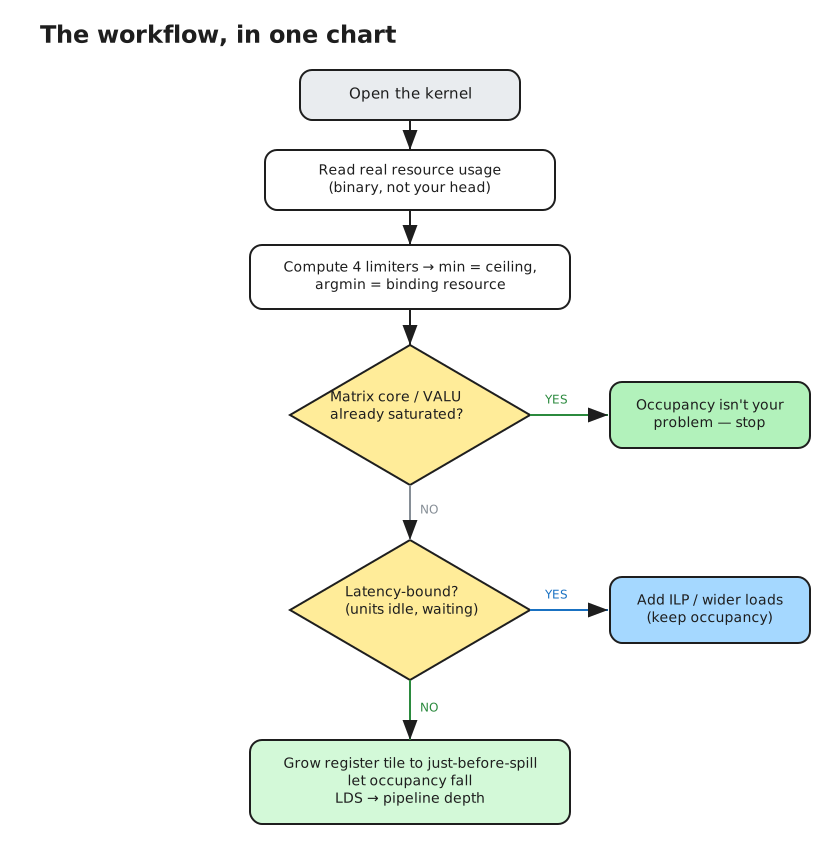
Figure 10: A kernel-tuning workflow — read real resource usage, compute the four limiters, check matrix-engine utilization, and decide whether you’re latency-bound (add ILP) or matrix-bound (grow the tile).#
The kernels that win on MI355X GPU treat the 512-VGPR file and the matrix core as the scarce resources — and treat occupancy as the readout that tells them which knob just moved. Compute the ceiling so you know where it is — then decide, deliberately, how far below it to stop. Every constant and limiter you need for that calculation is collected in the MI355X GPU occupancy cheat sheet in the appendix.
This post deliberately stopped at the microbenchmark, isolating the matrix engine from everything around it. The natural next step is the full GEMM: how ILP, tile size, and software-pipelined prefetch trade off against each other in a real HBM-fed kernel, and how the Gluon path we sketched here scales to production tiles. We plan to follow up with posts on tuning end-to-end MXFP8 GEMMs on CDNA4, XCD-aware scheduling for last-level-cache locality, and applying this same “feed the matrix core, don’t chase occupancy” lens to attention and MoE kernels. If this guide changed how you read an occupancy number, the follow-ups will show it paying off at scale.
Appendix: MI355X GPU Occupancy Cheat Sheet#
Note
MI355X GPU occupancy cheat sheet (gfx950, verified on-device) — 512 VGPR/lane per SIMD (private), shared by regular ≤256 + accumulator ≤256 · ~800 SGPR/SIMD, ≤102/wave · 160 KB LDS/CU (shared) · max 8 waves/SIMD, 32/CU · VGPR alloc granularity 8 · limiters: VGPR (regular+acc), SGPR, LDS, workgroup (+barriers) · occupancy = min(limiters), then clamp.
Additional Resources#
Vasily Volkov, “Better Performance at Lower Occupancy”, NVIDIA GTC 2010 — the original case that throughput can peak well below full occupancy when ILP, not more waves, hides latency. The argument this post carries onto CDNA4. [PDF]
AMD, “AMD Instinct CDNA4 Instruction Set Architecture Reference Guide” (Aug 2025) — source for the unified 512-entry-per-lane VGPR/AccVGPR file (§3.6.4), the eight-Dword allocation granularity, and the scaled-MFMA (
v_mfma_scale_f32_*_f8f6f4) instructions. [PDF]AMD, “Introducing AMD CDNA 4 Architecture” (whitepaper) — the MI355X GPU/CDNA4 hardware the math is built on: 256 compute units, 160 KB LDS/CU, the Matrix Core, and the ~5 PFLOP/s MXFP8 / 10 PFLOP/s MXFP6·FP4 peak rates. [PDF]
Disclaimers#
The information presented in this document is for informational purposes only and may contain technical inaccuracies, omissions, and typographical errors. The information contained herein is subject to change and may be rendered inaccurate for many reasons, including but not limited to product and roadmap changes, component and motherboard version changes, new model and/or product releases, product differences between differing manufacturers, software changes, BIOS flashes, firmware upgrades, or the like. Any computer system has risks of security vulnerabilities that cannot be completely prevented or mitigated. AMD assumes no obligation to update or otherwise correct or revise this information. However, AMD reserves the right to revise this information and to make changes from time to time to the content hereof without obligation of AMD to notify any person of such revisions or changes. THIS INFORMATION IS PROVIDED ‘AS IS.” AMD MAKES NO REPRESENTATIONS OR WARRANTIES WITH RESPECT TO THE CONTENTS HEREOF AND ASSUMES NO RESPONSIBILITY FOR ANY INACCURACIES, ERRORS, OR OMISSIONS THAT MAY APPEAR IN THIS INFORMATION. AMD SPECIFICALLY DISCLAIMS ANY IMPLIED WARRANTIES OF NON-INFRINGEMENT, MERCHANTABILITY, OR FITNESS FOR ANY PARTICULAR PURPOSE. IN NO EVENT WILL AMD BE LIABLE TO ANY PERSON FOR ANY RELIANCE, DIRECT, INDIRECT, SPECIAL, OR OTHER CONSEQUENTIAL DAMAGES ARISING FROM THE USE OF ANY INFORMATION CONTAINED HEREIN, EVEN IF AMD IS EXPRESSLY ADVISED OF THE POSSIBILITY OF SUCH DAMAGES. AMD, the AMD Arrow logo, and combinations thereof are trademarks of Advanced Micro Devices, Inc. Other product names used in this publication are for identification purposes only and may be trademarks of their respective companies. © 2026 Advanced Micro Devices, Inc. All rights reserved