Programming Tensor Descriptors in Composable Kernel (CK)#
")
Writing efficient GPU kernels requires more than knowing the API—it demands a deep understanding of the underlying concepts, from GPU architecture to low-level programming patterns. This blog series demystifies GPU kernel programming on AMD GPUs by breaking down common kernels into their fundamental building blocks. Rather than treating GPU programming as a black box, each blog focuses on a specific concept, starting from first principles and building up to complete implementations with simple, insightful example code. In this blog, you will learn one of the most fundamental concepts in Composable Kernel (CK): the TensorDescriptor—a powerful abstraction for managing multi-dimensional data layouts and transformations. By the end of this series, you will be able to not only understand existing GPU kernels but also design and optimize your own.
Tensor#
Conceptual Understanding#
Logically speaking, a Tensor can be understood as a mapping from logical coordinates to physical memory addresses. For example, if we define a K-dimensional Tensor \(T(d_1, d_2, d_3, ..., d_k)\), we can read and write elements within this Tensor as follows:
Assuming the data pointer of Tensor is P, and the stride for each dimension is \([s_1, s_2, ... s_k]\), then in terms of physical storage, the above data access translates to:
This demonstrates the fundamental mapping: logical multi-dimensional coordinates are converted to a single linear memory offset by taking the dot product of the coordinate vector with the stride vector. CK (Composable Kernel) needs to implement this mapping relationship efficiently.
TensorDescriptor#
Overview#
CK uses TensorDescriptor to define Tensors. The source code definition is as follows:
template <typename Transforms,
          typename LowerDimensionIdss,
          typename UpperDimensionIdss,
          typename VisibleDimensionIds,
          typename ElementSpaceSize>
struct TensorDescriptor
There are a few confusing concepts in the struct definition, we’ll explain them next. Let’s start with Transforms.
The Concept of Transform#
To understand TensorDescriptor, we need to introduce a core concept: Transform. In CK, a Transform is defined as a struct type. TensorDescriptor uses a tree structure composed of multi-level coordinates and multiple Transforms to represent a Tensor, as shown in Figure 1.
Each Transform defines a method called CalculateLowerIndex, which maps upper-level coordinates to lower-level coordinates. At the bottom level of the TensorDescriptor hierarchy, we have a one-dimensional coordinate that directly corresponds to physical memory storage. Through a series of Transforms, we can construct any desired target coordinate system from this base.
Example: Building a 3D Tensor from a 2D Base#
Let’s consider an example: we start with an (M, K) Tensor, then split the first dimension into two dimensions, resulting in a final (M1, M2, K) Tensor. If we represent this using CK’s TensorDescriptor, the data structure looks like this:
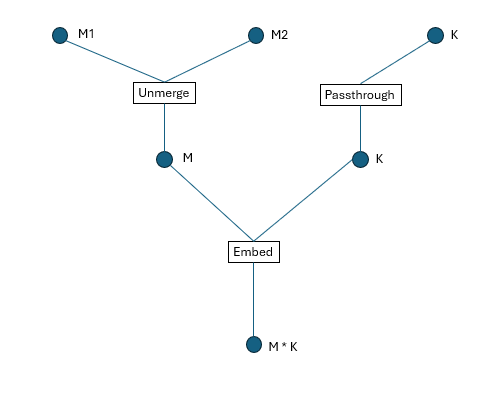
Figure 1. TensorDescriptor tree structure
Note: If we define a 2D tensor in CK, an instance of Transform named Embed will be implicitly inserted, as shown in Figure 1.
In the diagram:
Circle nodes represent dimensions/coordinates.
Square boxes represent Transforms.
Coordinate Mapping Process#
How do we map high-dimensional coordinates to physical addresses? Following the structure shown above, we execute each Transform’s CalculateLowerIndex method from top to bottom. For example, to map coordinates (a1, a2, a3) to a physical address, the process is illustrated in Figure 2, below:
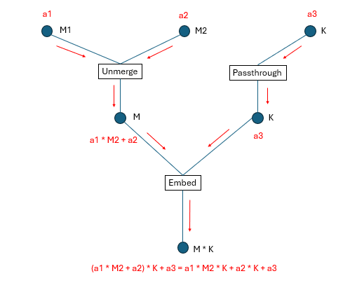
Figure 2: Coordinate transformation process
Dimension Indexing System#
If we assign a global index to each dimension (all the circles in the figure) shown in Figure 1, we obtain Figure 3:
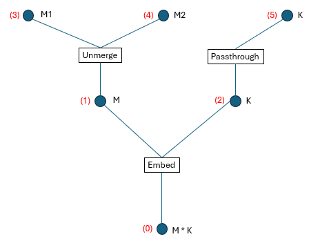
Figure 3: Global dimension numbering
We define the following terminology:
Upper dimension id: The dimension id(s) above each Transform.
Lower dimension id: The dimension id(s) below each Transform.
Visible dimension id: The dimension id(s) at the top level of the tree structure (what the user directly interacts with).
From Figure 3, we can extract four tuples that fully describe the TensorDescriptor:
Transforms = [Embed, Unmerge, Passthrough]
LowerDimensionIdss = [
    [0], [1], [2]
]
UpperDimensionIdss = [
    [1, 2],
    [3, 4],
    [5]
]
VisibleDimensionIds = [3, 4, 5]
For one specific Transform Transforms[i], its upper dimension ids are UpperDimensionIdss[i] and its lower dimension ids are LowerDimensionIdss[i].
These tuples encode:
Which transforms are applied.
How dimensions are connected between levels.
Which dimensions are exposed to the user.
Code Example#
Here’s a complete example demonstrating how to create and use TensorDescriptors:
 1  #include "ck/tensor_operation/gpu/device/impl/device_gemm_xdl_cshuffle.hpp"
 2  #include "ck/library/utility/literals.hpp"
 3  #include "ck/utility/functional3.hpp"
 4  #include "ck/utility/static_buffer.hpp"
 5  #include "ck/utility/tuple.hpp"
 6  #include "ck/tensor_description/tensor_descriptor_helper.hpp"
 7  #include "ck/tensor_operation/gpu/grid/gridwise_gemm_xdlops_bwd_weight.hpp"
 8
 9  int main() {
10      index_t M = 256, K = 128;
11
12      // Instantiate the Transform UnMerge to split the dimension M into (M1, M2).
13      // There are multiple ways to instantiate an Unmerge Transform
14      // auto unmerge = make_unmerge_transform(make_tuple(4, 64));
15      // auto up_lengths = make_tuple(4, 64);
16      // Tuple<Number<4>, Number<64>> up_lengths;
17      Tuple<int, int> up_lengths{4, 64};
18      UnMerge<decltype(up_lengths), false> unmerge{up_lengths};
19
20      // Try calling the CalculateLowerIndex method of UnMerge
21      // This maps coordinates (1, 3) to a single linear index
22      auto lower_idx = make_multi_index(0);
23      unmerge.CalculateLowerIndex(lower_idx, make_multi_index(1, 3));
24      printf("Unmerge lower_idx = %d\n", lower_idx[Number<0>{}]);
25
26      // For each layer of dimensions, unhandled dimensions have to be passed through an identity transform named PassThrough.
27      // There are multiple ways to instantiate a PassThrough Transform
28      // auto passthrough = make_pass_through_transform(K);
29      PassThrough<int> passthrough{K};
30
31      // Create a naive tensor descriptor (implicitly includes an Embed Transform)
32      // This creates a 2D tensor with row-major layout (stride K for rows, stride 1 for columns)
33      auto tensor_desc = make_naive_tensor_descriptor(make_tuple(M, K), make_tuple(K, 1));
34      printf(
35           "tensor_desc.shape = %d, %d\n",
36           tensor_desc.GetLength(Number<0>{}),
37           tensor_desc.GetLength(Number<1>{})
38      );
39
40      // When performing transforms, use logical dimension ids, not global dimension ids
41      // This transforms the (256, 128) tensor to (4, 64, 128)
42      // - Dimension 0 (size 256) is unmerged into dimensions (4, 64)
43      // - Dimension 1 (size 128) passes through unchanged
44      auto transformed_tensor_desc = transform_tensor_descriptor(
45           tensor_desc,
46           make_tuple(unmerge, passthrough),
47           make_tuple(Sequence<0>{}, Sequence<1>{}), // Lower dimension ids
48           make_tuple(Sequence<0, 1>{}, Sequence<2>{}) // Upper dimension ids
49      );
50      printf(
51           "transformed_tensor_desc.shape = %d, %d, %d\n",
52           transformed_tensor_desc.GetLength(Number<0>{}),
53           transformed_tensor_desc.GetLength(Number<1>{}),
54           transformed_tensor_desc.GetLength(Number<2>{})
55      );
56
57      // Calculate the physical offset for coordinate (1, 3, 2)
58      auto coord = make_multi_index(1, 3, 2);
59      printf("physical offset = %d\n", transformed_tensor_desc.CalculateOffset(coord));
60
61      // Get tensor coordinate which includes hidden intermediate dimension values
62      auto tensor_coord = make_tensor_coordinate(transformed_tensor_desc, coord);
63      auto hidden_idx = tensor_coord.GetHiddenIndex();
64      printf("hidden_idx = ");
65      static_for<0, hidden_idx.Size(), 1>{}([&](auto i){
66          printf("%d, ", hidden_idx[i]);
67      });
68      return 0;
69 }
After compiling and running, the output is:
Unmerge lower_idx = 67
tensor_desc.shape = 256, 128
transformed_tensor_desc.shape = 4, 64, 128
physical offset = 8578
hidden_idx = 8578, 67, 2, 1, 3, 2,
Understanding the Output#
Unmerge lower_idx = 67: When we unmerge coordinates (1, 3) with dimensions (4, 64), we get 1 * 64 + 3 = 67tensor_desc.shape = 256, 128: The original 2D tensor shapetransformed_tensor_desc.shape = 4, 64, 128: The transformed 3D tensor shape generated by splitting the first dimension (256) into two dimensions (4, 64)physical offset = 8578: The linear memory offset for coordinate (1, 3, 2), calculated as(1 * 64 + 3) * 128 + 2 = 67 * 128 + 2 = 8578hidden_idx: Contains values at all levels of the tree structure from Figure 3
Chaining Transforms#
We can continue to transform the tensor_desc. For example, let’s merge the second and third dimensions into a single dimension:
 1  // #include ...
 2
 3  int main() {
 4
 5      // ...
 6
 7      // Merge dimensions with sizes 64 and 128
 8      auto low_dims = make_tuple(64, 128);
 9      Merge_v4_no_carry<decltype(low_dims)> merge{low_dims};
10
11      // Transform: keep dimension 0 (size 4), merge dimensions 1 and 2 (64 * 128 = 8192)
12      auto new_transformed_tensor_desc = transform_tensor_descriptor(
13               transformed_tensor_desc,
14               make_tuple(make_pass_through_transform(4), merge),
15               make_tuple(Sequence<0>{}, Sequence<1, 2>{}), // Lower dimension ids
16               make_tuple(Sequence<0>{}, Sequence<1>{})     // Upper dimension ids
17       );
18       printf(
19           "new_transformed_tensor_desc.shape = %d, %d\n",
20           new_transformed_tensor_desc.GetLength(Number<0>{}),
21           new_transformed_tensor_desc.GetLength(Number<1>{})
22       );
23  }
The output is:
new_transformed_tensor_desc.shape = 4, 8192
This demonstrates the composability of transforms - we can chain multiple transformation operations to achieve complex tensor layout manipulations. The final shape (4, 8192) shows that we’ve successfully merged the (64, 128) dimensions into a single dimension of size 8192.
Key Takeaways#
TensorDescriptor provides a flexible way to represent complex tensor layouts through hierarchical transformations
Transforms are composable operations that map between coordinate spaces
Common transforms include:
Embed: Maps multi-dimensional coordinates to linear memory
Unmerge: Splits one dimension into multiple dimensions
Merge: Combines multiple dimensions into one
PassThrough: Preserves a dimension unchanged
The tree structure allows CK to efficiently compute physical memory offsets from logical coordinates
Transforms can be chained to build complex layouts from simpler ones
This design enables CK to handle various tensor layouts (row-major, column-major, tiled, etc.) in a unified and composable manner, which is essential for optimizing GPU kernel performance.
Example of Matrix Transpose#
Matrix Transpose Overview#
Matrix transpose is a fundamental operation in linear algebra where we swap rows and columns of a matrix. Given an input matrix A of shape (M, K), the transpose operation produces an output matrix \(A^T\) of shape (K, M), where \(A^T[i,j] = A[j,i]\).
In this example, we demonstrate an efficient GPU implementation using CK. The key idea is to leverage parallelism at multiple levels:
Each GPU thread processes a 4×4 sub-matrix
Threads are organized into blocks of 8×8 (64 threads per block)
Each block therefore processes a 32×32 tile of the input matrix
This approach is efficient because:
Vectorized memory access: We use vector loads/stores for coalesced global memory access
Register-level transpose: The 4×4 transpose happens entirely in registers (VGPRs)
Minimal synchronization: No shared memory or thread synchronization needed
The data processing of each thread is shown in Figure 4 below:
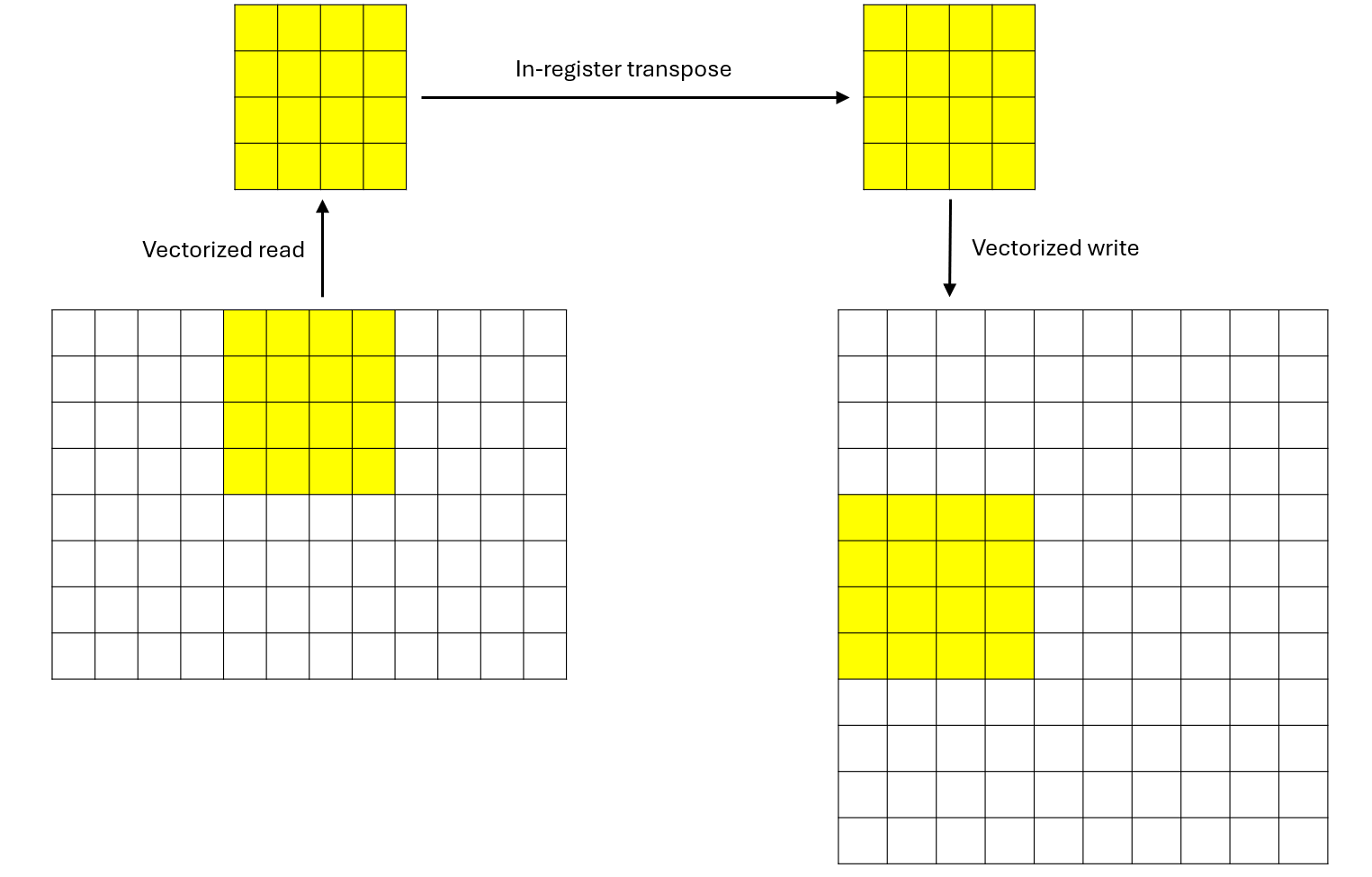
Figure 4: Data processing of each thread
There are 80 CUs on AMD MI308X. Please refer to the official AMD documentation for GPU architecture. Each block will occupy one CU. For demonstration purposes, we set M and K so that there are exactly 80 blocks to fully utilize the 80 CUs. Let’s say M = 80 * 32 = 2560 and K = 32.
This matrix transpose example demonstrates several key CK concepts:
Tensor descriptors: Clean abstraction for multi-dimensional data with arbitrary strides
Dynamic buffers: Type-safe GPU memory access with coordinate transformation
Compile-time loops:
static_forenables loop unrolling and optimizationVector types: Efficient vectorized memory operations
Register-level computation: Maximizing throughput by keeping data in registers
Host Code Walkthrough#
The host code sets up the data, launches the kernel, and verifies the results. We used some APIs in CK, such as HostTensorDescriptor and DeviceMem. They are self-explanatory in the code snippet below:
  1 void matrix_transpose() {
  2     // =================================================
  3     // STEP 1: Define Matrix Dimensions
  4     // =================================================
  5     // We'll transpose a 2560×32 matrix to a 32×2560 matrix
  6     // M = number of rows, K = number of columns
  7     index_t M = 2560;
  8     index_t K = 32;
  9
 10     // =================================================
 11     // STEP 2: Create and Initialize Host (CPU) Input Tensor
 12     // =================================================
 13     // Create a host tensor descriptor with:
 14     //   - Shape: {M, K} = {2560, 32}
 15     //   - Strides: {K, 1} = {32, 1} (row-major layout)
 16     HostTensorDescriptor host_desc{{M, K}, {K, 1}};
 17
 18     // Allocate the host tensor using the descriptor
 19     Tensor<float> host_tensor(host_desc);
 20
 21     // Fill the tensor with random integer values between -5 and 5
 22     // This helps with debugging (integer values are easier to verify)
 23     ck::utils::FillUniformDistributionIntegerValue<float>{-5.f, 5.f}(host_tensor);
 24
 25     // =================================================
 26     // STEP 3: Allocate Device (GPU) Memory and Copy Input Data
 27     // =================================================
 28     // Allocate GPU memory for the input matrix
 29     // Size = number of elements × size of each element
 30     DeviceMem device_buf(sizeof(float) * host_tensor.mDesc.GetElementSpaceSize());
 31
 32     // Copy data from host to device (CPU → GPU)
 33     device_buf.ToDevice(host_tensor.mData.data());
 34
 35     // =================================================
 36     // STEP 4: Create and Allocate Host/Device Output Tensor
 37     // =================================================
 38     // Create descriptor for the TRANSPOSED output matrix
 39     // Note: dimensions are swapped from {M, K} to {K, M}
 40     //   - Shape: {K, M} = {32, 2560}
 41     //   - Strides: {M, 1} = {2560, 1} (row-major layout)
 42     HostTensorDescriptor ret_desc{{K, M}, {M, 1}};
 43
 44     // Allocate the host output tensor
 45     Tensor<float> ret_tensor(ret_desc);
 46
 47     // Allocate GPU memory for the output matrix
 48     DeviceMem ret_buf(sizeof(float) * ret_tensor.mDesc.GetElementSpaceSize());
 49
 50     // Initialize GPU output buffer with host data (zeros initially)
 51     ret_buf.ToDevice(ret_tensor.mData.data());
 52
 53     // =================================================
 54     // STEP 5: Configure Kernel Launch Parameters
 55     // =================================================
 56     // Block dimension: 8×8 threads = 64 threads per block
 57     // Each thread processes a 4×4 sub-matrix
 58     // Therefore, each block processes a 32×32 tile (8×4 = 32 in each dimension)
 59     dim3 blockDim{8, 8};
 60
 61     // =================================================
 62     // STEP 6: Launch the Kernel
 63     // =================================================
 64     // Grid dimension calculation:
 65     //   - Each block handles 32 rows (8 threads × 4 rows per thread)
 66     //   - Total rows: M = 2560
 67     //   - Grid size: M / 32 = 2560 / 32 = 80 blocks
 68     //   - Equivalently: M / 8 / 4 = 2560 / 8 / 4 = 80
 69     //
 70     // Launch configuration summary:
 71     //   - Grid: 80 blocks
 72     //   - Block: 8×8 = 64 threads
 73     //   - Total threads: 80 × 64 = 5,120 threads
 74     //   - Work per thread: 4×4 = 16 elements
 75     //   - Total elements: 5,120 × 16 = 81,920 = 2560 × 32 ✓
 76     matrix_transpose_kernel<<<M / 8 / 4, blockDim, 0, 0>>>(
 77         (float*)device_buf.GetDeviceBuffer(),   // Input: M×K matrix
 78         (float*)ret_buf.GetDeviceBuffer(),      // Output: K×M matrix
 79         M, K                                      // Dimensions
 80     );
 81
 82     // =================================================
 83     // STEP 7: Copy Results Back and Verify
 84     // =================================================
 85     // Copy the transposed matrix from GPU back to CPU
 86     ret_buf.FromDevice(ret_tensor.mData.data());
 87
 88     // Print a 6×6 sample of the input matrix
 89     printf("host_tensor: \n");
 90     for (int i = 0; i < 6; i++) {
 91         for (int j = 0; j < 6; j++) {
 92             // Access: row i, column j in row-major layout (stride = K)
 93             printf("%f, ", host_tensor.mData[i * K + j]);
 94         }
 95         printf("\n");
 96     }
 97
 98     // Print a 6×6 sample of the output (transposed) matrix
 99     printf("ret_tensor: \n");
100     for (int i = 0; i < 6; i++) {
101         for (int j = 0; j < 6; j++) {
102             // Access: row i, column j in row-major layout (stride = M)
103             printf("%f, ", ret_tensor.mData[i * M + j]);
104         }
105         printf("\n");
106     }
107
108     printf("matrix_transpose done\n");
109 }
Kernel Implementation Walkthrough#
Here’s the complete kernel with detailed inline comments explaining each step:
  1 __global__ void matrix_transpose_kernel(float * src, float * dst, index_t M, index_t K) {
  2     // =================================================
  3     // STEP 1: Tensor Descriptor Setup
  4     // =================================================
  5     // Create a row-major tensor descriptor for the input matrix
  6     // - Shape: (M, K)
  7     // - Strides: (K, 1) means row-major layout
  8     // - Element at (i, j) is at offset i * K + j
  9     auto tensor_desc = make_naive_tensor_descriptor(make_tuple(M, K), make_tuple(K, 1));
 10
 11     // Wrap the raw pointer with a dynamic buffer abstraction
 12     // This provides type-safe access with coordinate transformation
 13     auto buf = make_dynamic_buffer<AddressSpaceEnum::Global>(
 14             src, tensor_desc.GetElementSpaceSize());
 15
 16     // Create descriptor for the output (transposed) matrix
 17     // - Shape: (K, M) - dimensions are swapped
 18     // - Strides: (M, 1) - still row-major layout
 19     // - Element at (i, j) is at offset i * M + j
 20     auto ret_desc = make_naive_tensor_descriptor(make_tuple(K, M), make_tuple(M, 1));
 21
 22     // Wrap the output buffer
 23     auto ret_buf = make_dynamic_buffer<AddressSpaceEnum::Global>(
 24             dst, ret_desc.GetElementSpaceSize());
 25
 26     // =================================================
 27     // STEP 2: Compute Thread's Data Region
 28     // =================================================
 29     // Each thread processes a 4×4 sub-matrix
 30     // x: column offset (starting position in the column dimension)
 31     // y: row offset (starting position in the row dimension)
 32     //
 33     // Breaking down x calculation:
 34     //   - blockIdx.x * 8 * 4: Block's column offset (each block spans 32 columns)
 35     //   - threadIdx.x * 4: Thread's column offset within block (0, 4, 8, ..., 28)
 36     //
 37     // Breaking down y calculation:
 38     //   - threadIdx.y * 4: Thread's row offset within block (0, 4, 8, ..., 28)
 39     int x = (blockIdx.x * 8 + threadIdx.x) * 4, y = threadIdx.y * 4;
 40
 41     // =================================================
 42     // STEP 3: Allocate Thread-Local Storage (VGPRs)
 43     // =================================================
 44     // Allocate 16 floats in registers to hold our 4×4 sub-matrix
 45     // This is stored in Vector General Purpose Registers (VGPRs) on the GPU
 46     vector_type<float, 16> thread_local_buf;
 47
 48     // Create a view of the buffer as 4 vectors of 4 elements each (d4_t)
 49     // This enables vectorized memory access patterns
 50     // a[0] = 4 floats, a[1] = 4 floats, a[2] = 4 floats, a[3] = 4 floats
 51     auto& a = thread_local_buf.AsType<vector_type<float, 16>::d4_t>();
 52
 53     // =================================================
 54     // STEP 4: Read Input Data (4×4 Sub-Matrix)
 55     // =================================================
 56     // Read 4 rows from the input matrix, each containing 4 consecutive elements
 57     // This is a compile-time loop that will be fully unrolled
 58     //
 59     // Memory access pattern:
 60     //   i=0: Read row y,   columns [x, x+1, x+2, x+3] → store in a[0]
 61     //   i=1: Read row y+1, columns [x, x+1, x+2, x+3] → store in a[1]
 62     //   i=2: Read row y+2, columns [x, x+1, x+2, x+3] → store in a[2]
 63     //   i=3: Read row y+3, columns [x, x+1, x+2, x+3] → store in a[3]
 64     //
 65     // The Get<d4_t> performs a vectorized read of 4 consecutive floats,
 66     // which is efficient for coalesced memory access (threads in a warp
 67     // access consecutive memory locations)
 68     static_for<0, 4, 1>{}([&](auto i){
 69         a(Number<i>{}) = buf.Get<vector_type<float, 16>::d4_t>(
 70             tensor_desc.CalculateOffset(Tuple<int, int>{x + i, y}), true);
 71     });
 72
 73     // =================================================
 74     // STEP 5: In-Register Transpose
 75     // =================================================
 76     // Now we transpose the 4×4 matrix stored in registers
 77     // Create a view of the buffer as 16 individual floats (d1_t)
 78     auto& b = thread_local_buf.AsType<vector_type<float, 16>::d1_t>();
 79
 80     // Perform in-place transpose by swapping elements across the diagonal
 81     // Algorithm: swap b[i*4 + j] ↔ b[j*4 + i] for all i > j
 82     //
 83     // Visual representation of swaps:
 84     //   [0 1 2 3 ]          [0 4 8 12]
 85     //   [4 5 6 7 ] --> [1 5 9 13]
 86     //   [8 9 10 11]         [2 6 10 14]
 87     //   [12 13 14 15]       [3 7 11 15]
 88     //
 89     // Swap sequence:
 90     //   i=1, j=0: Swap b[4] ↔ b[1]
 91     //   i=2, j=0: Swap b[8] ↔ b[2]
 92     //   i=2, j=1: Swap b[9] ↔ b[5]
 93     //   i=3, j=0: Swap b[12] ↔ b[3]
 94     //   i=3, j=1: Swap b[13] ↔ b[7]
 95     //   i=3, j=2: Swap b[14] ↔ b[11]
 96     static_for<0, 4, 1>{}([&](auto i){
 97         static_for<0, i, 1>{}([&](auto j){
 98             auto tmp = b(Number<i * 4 + j>{});
 99             b(Number<i * 4 + j>{}) = b(Number<j * 4 + i>{});
100             b(Number<j * 4 + i>{}) = tmp;
101         });
102     });
103
104     // =================================================
105     // STEP 6: Write Output Data
106     // =================================================
107     // Write the transposed 4×4 sub-matrix to the output matrix
108     //
109     // CRITICAL: Note the coordinate swap!
110     //   - Input read position: (x+i, y) - we read rows from columns x through x+3
111     //   - Output write position: (y+i, x) - we write to the TRANSPOSED location
112     //
113     // This means:
114     //   - Input element at (x+i, y+j) is written to output at (y+j, x+i)
115     //   - What were columns in input become rows in output
116     //
117     // Memory write pattern:
118     //   i=0: Write row y,   columns [x, x+1, x+2, x+3] from a[0]
119     //   i=1: Write row y+1, columns [x, x+1, x+2, x+3] from a[1]
120     //   i=2: Write row y+2, columns [x, x+1, x+2, x+3] from a[2]
121     //   i=3: Write row y+3, columns [x, x+1, x+2, x+3] from a[3]
122     //
123     // The Set<d4_t> performs a vectorized write of 4 consecutive floats
124     static_for<0, 4, 1>{}([&](auto i){
125         ret_buf.Set<vector_type<float, 16>::d4_t>(
126             ret_desc.CalculateOffset(Tuple<int, int>{y + i, x}), true, a(Number<i>{}));
127     });
128 }
Notice the vector_type<float, 16>. It will allocate a buffer containing 16 float numbers in registers. The method thread_local_buf.AsType can view this buffer as different shapes. static_for is used for compile-time unrolling loops.
Performance Test#
For comparison, we implement matrix transpose in PyTorch and test the performance of both implementations with rocprofv3:
1  import torch
2
3  a = torch.randn([2560, 32], dtype=torch.float32).cuda()
4  b = a.transpose(0, 1).contiguous()
The performance of the PyTorch implementation is 8.4 μs and that of our CK implementation is 5.820 μs. This represents a 44.3% throughput improvement.
Summary#
In this blog, you learned the fundamentals of AMD GPU kernel programming using Composable Kernel (CK). Specifically, you explored:
TensorDescriptor: How CK uses a tree of hierarchical transforms to map logical multi-dimensional coordinates to physical memory addresses, providing a flexible and composable abstraction for complex tensor layouts.
Core transforms: The roles of Embed, Unmerge, Merge, and PassThrough transforms, and how they can be chained to build arbitrarily complex data layouts from simple building blocks.
Practical GPU kernel development: A complete matrix transpose implementation that leverages vectorized memory access, register-level computation, and compile-time loop unrolling for efficient execution on AMD GPUs.
The 4x4 per-thread transpose approach demonstrated here strikes a good balance between parallelism, memory efficiency, and register usage, making it an excellent template for similar GPU kernels.
In the next blog in this series, we will break down GEMM (General Matrix Multiply) into basic parts and understand them one by one, building on the TensorDescriptor foundation covered here. Stay tuned to continue your journey from beginner to expert in AMD GPU programming.
Acknowledgement#
We would like to express our thanks to AMD Quark Team for their insightful feedback and technical assistance.
Disclaimers#
Third-party content is licensed to you directly by the third party that owns the content and is not licensed to you by AMD. ALL LINKED THIRD-PARTY CONTENT IS PROVIDED “AS IS” WITHOUT A WARRANTY OF ANY KIND. USE OF SUCH THIRD-PARTY CONTENT IS DONE AT YOUR SOLE DISCRETION AND UNDER NO CIRCUMSTANCES WILL AMD BE LIABLE TO YOU FOR ANY THIRD-PARTY CONTENT. YOU ASSUME ALL RISK AND ARE SOLELY RESPONSIBLE FOR ANY DAMAGES THAT MAY ARISE FROM YOUR USE OF THIRD-PARTY CONTENT.