Two Waves, One Stage Apart: Warp-Pipelining Triton GEMMs on AMD Instinct#

A tiled general matrix multiplication (GEMM) computes on one pair of operand tiles while preparing the next. On a compute-bound shape, keeping the matrix units busy depends on how well those activities overlap. A common failure mode is that resident waves reach synchronization points in phase: both prepare data or wait, and neither has matrix work ready to issue. Extra buffering creates room for future tiles, but does not by itself establish the execution timing needed to hide that preparation.
Warp-pipelining is a user-directed scheduling technique in the Triton AMD backend. It holds two wave groups one stage apart, where each stage groups related compute or data-preparation operations. With balanced stages and ready operands, one group can issue matrix work while the other moves data or calculates addresses. Barriers maintain this offset, while the workload determines how much preparation can be hidden.
In this blog, you will learn how stage annotations and barriers keep two wave groups one stage apart, how to place waits around their shared-memory dependencies, and how the schedule adapts to MI300X, MI350, and MI450. You will also find public kernel examples and commands for exploring the technique on compute-bound GEMMs.
On the MI355X FP16 GEMM considered here, at M=N=4096, K=8192, an 8-wave
warp-pipelined kernel reaches 1,437 TFLOP/s, compared with 1,425
TFLOP/s for a hand-tuned 4-wave kernel. We interpret that small difference
as parity. Neither kernel spills. The 8-wave kernel expresses its schedule
through stage annotations, providing a way to approach hand-tuned performance
with a schedule the kernel author can describe and the compiler can preserve.
Triton uses warp in its API. AMD executes wavefronts, called waves below. Local Data Share (LDS) is workgroup-shared memory, while vector general-purpose registers (VGPRs) hold per-lane values. Matrix instructions are Matrix Fused Multiply-Add (MFMA) on the earlier targets and Wave Matrix Multiply-Accumulate (WMMA) on MI450. The examples primarily target compute-bound GEMM shapes with enough matrix work to cover data preparation.
Why the Matrix Pipeline Drains#
In the reference 8-wave launch, each of four SIMD units hosts two waves from the workgroup. Those waves share matrix-issue capacity. If both run the same phase of the loop, their matrix work competes for that capacity, followed by a period when both are preparing data. Workgroup barriers can repeatedly bring the waves back into phase even if instruction scheduling previously separated them.
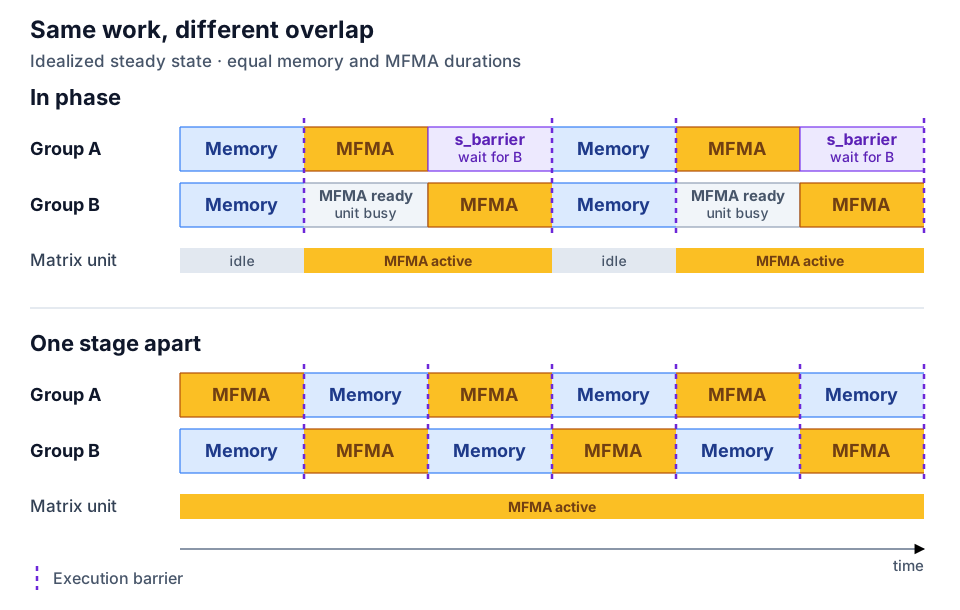
Figure 1. In-phase and offset schedules for the same work.#
The operation times in Figure 1 are identical in both panels. In the
in-phase case, Group A finishes MFMA first and waits at s_barrier for Group
B. It starts memory work as soon as the barrier releases, with no additional
wait before memory. The offset schedule covers memory preparation with matrix
work in its steady state.
If preparation takes longer than the matrix stage, the compute group reaches the next rendezvous and waits. The offset makes overlap possible without making either stage faster. Here, overlap means instructions are in flight together or one wave can issue useful work while another waits. It does not imply that both waves issue matrix instructions in the same cycle.
The barrier instructions used for these rendezvous depend on the target. On
GFX9-class targets, s_barrier combines arrival and waiting. Newer targets,
including MI450’s gfx1250, provide separate s_barrier_signal and
s_barrier_wait operations, allowing independent instructions between them.
Split-barrier scheduling and warp-pipelining can therefore complement each
other.
Two Waves, One Stage Apart#
Both wave groups execute the same staged loop. The compiler delays Group B before entry, then uses each stage boundary as a rendezvous between groups that are at different program points. This maintains a one-stage offset in program progress, rather than a fixed delay measured in cycles.
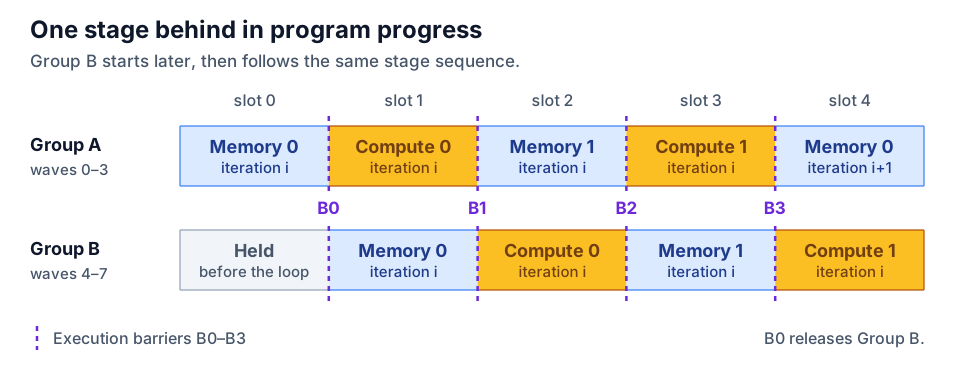
Figure 2. Two wave groups separated by one stage.#
Group A contains waves 0–3 and Group B waves 4–7. Each SIMD carries one wave from each group. The stage slots in the schematic show execution order. Actual slot times depend on the work and waits in both groups.
Creating and Closing the Offset#
The Triton AMD operation amdg.cond_barrier executes a barrier when its
predicate is true and skips it otherwise. Before the loop, Group B waits at
that barrier while Group A continues. Group A’s first in-loop arrival releases
Group B, establishing the offset. Subsequent stage-boundary arrivals preserve
it. After the loop, the complementary predicate makes Group A wait for Group
B’s final in-loop arrival, closing the offset.
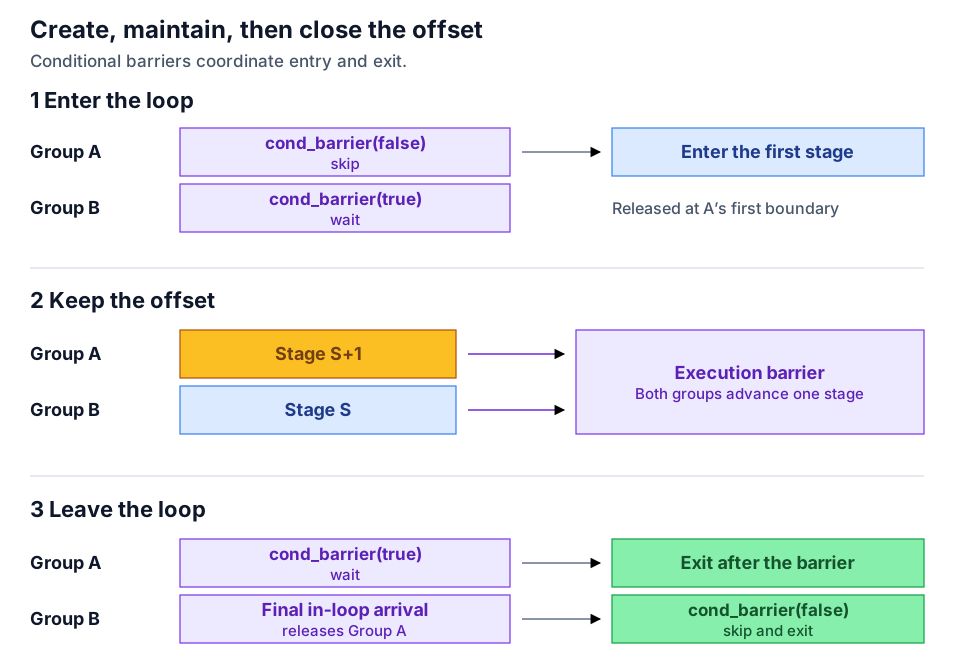
Figure 3. Entering, running, and leaving the staged loop.#
The predicates must be uniform within each wave. Across the full loop, both groups must participate in matching barrier phases, including the entry and exit barriers. This keeps their progress coordinated even though they reach each rendezvous from different stages.
At every stage boundary, the execution barrier maintains the offset between wave groups. Memory ordering is a separate requirement: shared-memory writes must finish before another group reads the data, and reads must finish before the buffer is reused. The compiler must add completion waits where these dependencies require them. Unnecessary waits at other boundaries can reduce overlap.
Writing a Warp-Pipelined Loop#
Gluon, Triton’s language with explicit tensor layouts, exposes stages through
warp_pipeline_stage. This simplified MI350-style body illustrates the
ordering. Prologue, buffer indexing, and address updates are omitted:
from triton.experimental.gluon.language.amd import warp_pipeline_stage
from triton.experimental.gluon.language.amd.cdna4 import async_copy as cdna4_async
from triton.experimental.gluon.language.amd.cdna4 import mfma as mfma_cdna4

for _ in range(0, loop_ub):
    # Close the cross-group LDS hazard one stage before the load below.
    cdna4_async.wait_group(wait_count)

    with warp_pipeline_stage("mfma", priority=0):
        acc = mfma_cdna4(a, b, acc)

    with warp_pipeline_stage("memory", priority=1):
        a, b = load_next_operands_from_lds(...)
        issue_and_commit_async_copy_for_future_tile(...)
The wait comes before MFMA because the later LDS read needs data copied by both groups. When Group A reaches the read, Group B is still in the preceding stage. Waiting for copies immediately before each group’s own read would let Group A proceed while Group B’s copy could still be incomplete. Placing the wait one stage earlier ensures that Group B completes its copy before the rendezvous releases Group A into the read stage. Figure 10 shows this dependency across the two timelines.
The labels identify stages in compiler diagnostics. The stage regions group operations, constrain compiler motion, and provide the units for dependency analysis. The memory stage’s higher priority helps its address-generation work compete for issue slots. Priority is a scheduling hint and should be tuned together with stage size.
The reference launch uses num_warps=8 and waves_per_eu=2. The latter is a
compiler occupancy hint, while actual register and LDS use determine
residency.
To complete the loop, a prologue fills the initial buffers and an epilogue consumes the remaining tiles after the groups meet again. In this pattern, async waits sit outside the annotated stages so their placement can account for dependencies between the groups.
What Lands in the Instruction Stream#
Two controls preserve a stage boundary: a compiler scheduling wall prevents unwanted instruction motion, and an execution barrier coordinates the waves. For a boundary requiring an LDS completion wait, the sequence can look like:
; schematic GFX9 boundary, not a verbatim compiler dump
    ...                       ; memory/preparation work
    s_waitcnt lgkmcnt(0)       ; required LDS completion, if any
    [sched.barrier(0)]         ; compiler scheduling wall; no ISA encoding
    s_barrier                 ; runtime rendezvous
    [sched.barrier(0)]
    v_mfma_...
    v_mfma_...
In this example, the two llvm.amdgcn.sched.barrier(0) markers keep the
preparation instructions above the boundary and the MFMA instructions below it
during compiler scheduling. The markers are removed before machine code is
emitted. At runtime, s_barrier coordinates the wave groups, while
s_waitcnt ensures the required LDS operations have completed.
A Historical Prototype: The Wormhole#
An early prototype demonstrated this offset by routing both groups through a helper containing one barrier instruction. Nicknamed the wormhole, the helper was called from different stages in the two groups. Each group then returned to its own timeline, still one stage apart.
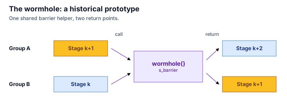
Figure 4. The wormhole helper in the historical prototype.#
The helper was one way to express the offset using the available barrier instructions. Stage annotations separate that scheduling pattern from the hardware instructions used to implement it. A backend can map stage boundaries to its target’s barriers and memory-ordering operations. This separation makes it possible to extend warp-pipelining to different barrier hardware, including non-AMD GPUs, through target-specific lowering.
Seeing the Offset in a Trace#
An Advanced Thread Trace (ATT) of the MI355X kernel shows how the stage offset translates into wave activity.
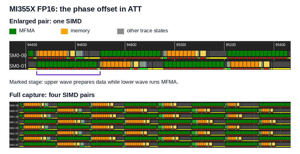
Figure 5. MI355X FP16 wave overlap in Advanced Thread Trace (ATT).#
The bracket below the enlarged trace marks one preparation stage in the upper wave, overlapping MFMA work in the lower wave. The full capture shows the alternating pattern across four SIMD pairs. Throughput and matrix efficiency quantify the benefit over a longer interval.
GEMM Results Across Three Generations#
The same scheduling idea adapts to each generation’s data-movement hardware. The results below report throughput alongside in-loop, per-SIMD matrix efficiency: the ideal cycles needed to issue the observed matrix work, divided by the elapsed cycles in the measured issue region. For an 8-wave kernel, work from both resident waves contributes to the numerator.
Matrix efficiency describes the measured loop region, rather than the whole kernel or a percentage of advertised peak FLOP/s. Prologue, epilogue, clock frequency, and memory behavior also affect throughput.
MI300X (gfx942, CDNA 3): One LDS Buffer#
For the reference MI300X kernel, tiles follow this path:
HBM -> VGPR -> LDS -> VGPR -> MFMA
A 256x256x64 FP16/BF16 tile needs 64 KiB of LDS for its A and B operands,
leaving no room for a second full buffer. VGPRs hold future global loads while
the single LDS buffer is consumed and then refilled in place.
The BlockPingpong compiler pass, introduced in
Triton PR #5018 in 2024,
was the first implementation of warp-pipelining in Triton. It split dot
operations into smaller slices, interleaved memory work, and inserted
barriers and priority changes to keep the two wave groups offset. The pass
depended on specific tile shapes, dot lowering, and wait placement.
Source-level stage annotations made the same scheduling idea easier to apply
to other kernel structures.
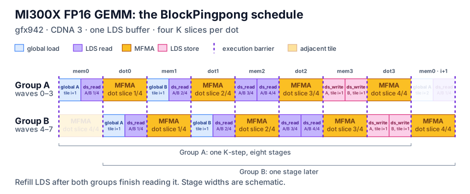
Figure 6. The MI300X BlockPingpong schedule.#
The pass’s transformFourPPClusters routine splits the dot along K into four
slices, as shown in Figure 6. The memory stages read the current tile and
fetch the next one. The final memory stage refills LDS after both groups have
finished reading its old contents. The newer stage-based 8-wave kernel uses
exactly 64 KiB of LDS, has no spills, and the measured dispatch reports no LDS
bank conflicts.
At M=4096, N=4864, the grid contains 304 workgroups for 304 CUs. Across
the measured K range, the BF16 kernel sustains 96.71%–99.42% in-loop MFMA
efficiency. At K=16448, it reaches 689.9 TFLOP/s, compared with 627.2
TFLOP/s for PyTorch matmul through hipBLASLt and 678.6 TFLOP/s for the tuned
4-wave kernel, whose MFMA efficiency is 89.63%. The warp-pipelined kernel
exceeds hipBLASLt on all eight measured FP16/BF16 points.
For historical context, BlockPingpong reaches 543.0 TFLOP/s and 95.84% MFMA
efficiency at FP16 4096x4864x8256. The stage-based kernel reaches 598.3
TFLOP/s and 97.81%. Different MFMA instruction shapes affect clock and power,
so this comparison describes the evolution rather than isolating one change.
The comparison with the tuned 4-wave kernel also shows why fewer cycles do not
always mean higher throughput. At FP16 K=8256, the 8-wave kernel needs
4187.7 cycles per K-step versus 4587.7 for the 4-wave kernel and improves MFMA
efficiency from 89.28% to 97.81%, yet reports lower TFLOP/s. Power and thermal
conditions can lower the sustained clock enough to offset a cycle advantage.
Read cycle counts together with clock samples and elapsed time.
MI350 Series (gfx950, CDNA 4): Three Overlapping Flows#
The MI350 Series adds direct asynchronous global-to-LDS copies and 160 KiB of LDS. The reference kernel uses separate, double-buffered allocations for its operand halves. Three flows can overlap: copies for a future tile, LDS reads for the next matrix operation, and MFMA for the current one.
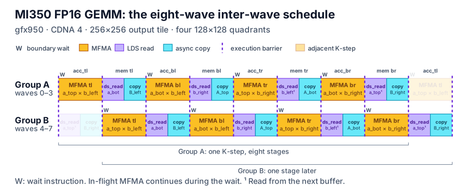
Figure 7. One MI350 K-step. Two K-steps form the unrolled loop.#
Each 256x256 output tile has four 128x128 quadrants. Each quadrant gets
one MFMA stage and one memory stage: eight annotated stages per K-step, or 16
per iteration of the twice-unrolled loop. These boundaries also leave room for
the memory group to issue vector arithmetic logic unit (VALU) instructions for
address generation. The W markers identify wait instructions, during which
MFMA already in flight can continue executing. The early waits protect
subsequent LDS reads, and separate allocations help analysis distinguish
refills from independent reads.
On MI355X at FP16 M=N=4096, K=16384, the 8-wave kernel reaches 1,485
TFLOP/s with 99.8% in-loop MFMA efficiency and no spills. At K=8192,
it reaches 1,437 TFLOP/s at 99.8%, compared with 1,425 TFLOP/s at
98.7% for the tuned 4-wave kernel. The small throughput difference is
interpreted as parity for this comparison.
This comparison measures two optimized implementations with different wave
counts, layouts, and compiler settings. It does not measure the effect of
changing only warp-pipelining. The 4-wave implementation uses an LLVM
intermediate representation (LLIR) scheduler, forced accumulator-register
(AGPR) allocation, and an amdgcnas assembly peephole pass. The 8-wave
implementation reaches comparable throughput through the staged schedule. The
relative performance still depends on the shape and compiler configuration.
MI450 (gfx1250, CDNA 5): TDM and Clustered Execution#
MI450 uses a Tensor Data Mover (TDM) for descriptor-based asynchronous transfers into LDS. Workgroup-addressable LDS grows to 320 KiB, waves have 32 lanes, and matrix computation uses WMMA. The maximum addressable vector-register allocation per wave grows from 512 combined VGPR/AGPR registers to 1024 unified VGPRs.
An 8-wave workgroup still divides into two groups of four waves, now with 128 threads per group instead of 256. The compiler uses the target wave size to form the groups, allowing the same stage representation to carry over. Data movement, layouts, and useful stage boundaries remain target-specific.
The BF16, MXFP8, and MXFP4 examples use eight waves, two LDS buffers, and 4x4
clusters of 16 workgroups. A 256x256 output tile per workgroup gives a
1024x1024 aggregate cluster tile. Their performance combines four
techniques:
Warp-pipelining overlaps matrix work with reads, refill, and synchronization.
Leading-group TDM performs data transfers on waves 0–3. Both groups compute.
Partition-aware LDS layouts reduce conflicts between SIMD pairs.
Cluster multicast lets a transfer serve multiple workgroups.
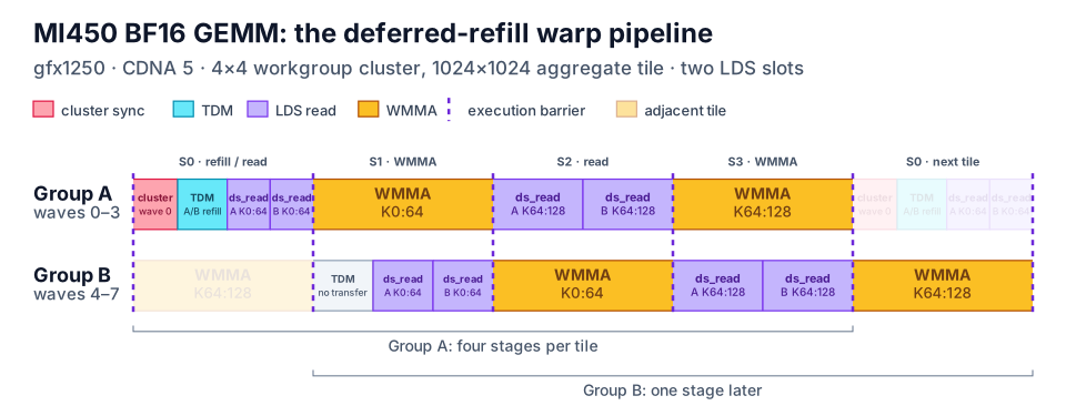
Figure 8. The MI450 BF16 deferred-refill schedule.#
The illustrated schedule consumes a tile in two matrix stages, each covering a
K64 slice. In stage S0, wave 0 alone issues the cluster arrival and wait.
Group A refills the reusable LDS slot, while operand reads use the active
slot. Stage S2 reads the second K64 slice. Both groups execute TDM
instructions, but only Group A performs the data transfers.
Both groups still execute the WMMA stages, so selective TDM transfers do not assign them permanent producer and consumer roles. Cluster synchronization controls buffer reuse across workgroups, while stage rendezvous control the offset within each workgroup. Figure 8 shows this stage order without representing instruction latencies or every cluster-barrier operation.
For the LDS layout details, see the companion post, A Deep Dive into LDS Optimizations on AMD Instinct MI450 GPUs.
At M=N=4096, K=65536, the reference measurements compare the combined
optimizations with hipBLASLt:
Data type |
hipBLASLt |
Warp-pipelined Triton |
Relative latency |
|---|---|---|---|
BF16 |
662.80 µs, 3.318 PFLOP/s (solution 114) |
684.71 µs, 3.212 PFLOP/s |
3.30% higher |
MXFP8 |
267.26 µs, 8.228 PFLOP/s (solution 222) |
266.09 µs, 8.264 PFLOP/s |
0.44% lower |
MXFP4 |
140.22 µs, 15.683 PFLOP/s (solution 153) |
140.80 µs, 15.618 PFLOP/s |
0.42% higher |
Table 1. MI450 GEMM results. Relative latency is measured against hipBLASLt.
Percentages are approximate. Throughput uses 2MNK / elapsed time.
The sub-percent MXFP differences are interpreted as parity in these measurements, while BF16 has higher latency. A separate BF16 ATT capture reports 95.22% in-loop WMMA efficiency. These results measure the complete kernels, including clustering and LDS layout choices. They do not isolate the contribution of warp-pipelining.
What the Compiler Has to Preserve#
These hardware-specific schedules rely on the compiler to preserve stage boundaries and the data dependencies between wave groups.
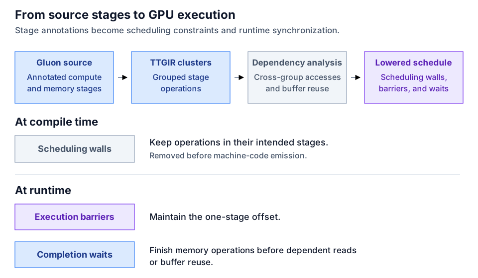
Figure 9. How the compiler preserves a staged schedule.#
Gluon lowering groups each stage’s operations into a compiler cluster in
Triton GPU IR (TTGIR) and marks the loop as warp-pipelined. The warp-pipeline
conversion analyzes memory accesses between these clusters and across loop
iterations. It selects the required synchronization, while scheduling walls
keep operations in their intended stages. This analysis works with Triton’s
general memory-barrier analysis (Membar) and target lowering to enforce
memory ordering for the staggered wave groups.
Avoiding Unnecessary Waits#
When independent ring buffers share one allocation, the compiler may be unable to prove that a read from one buffer is independent of a write to another. It can then insert an unnecessary completion wait before a matrix stage, delaying matrix instructions whose operands are already ready. Giving independent buffers separate allocations helps the compiler distinguish their accesses and avoid that wait. It must still retain waits for reads, writes, and buffer reuse that depend on one another.
Inspect the generated IR or ISA to check that waits protect actual shared-data dependencies. A kernel can produce correct results yet lose overlap because of unnecessary waits.
Dependencies Cross Groups and Iterations#
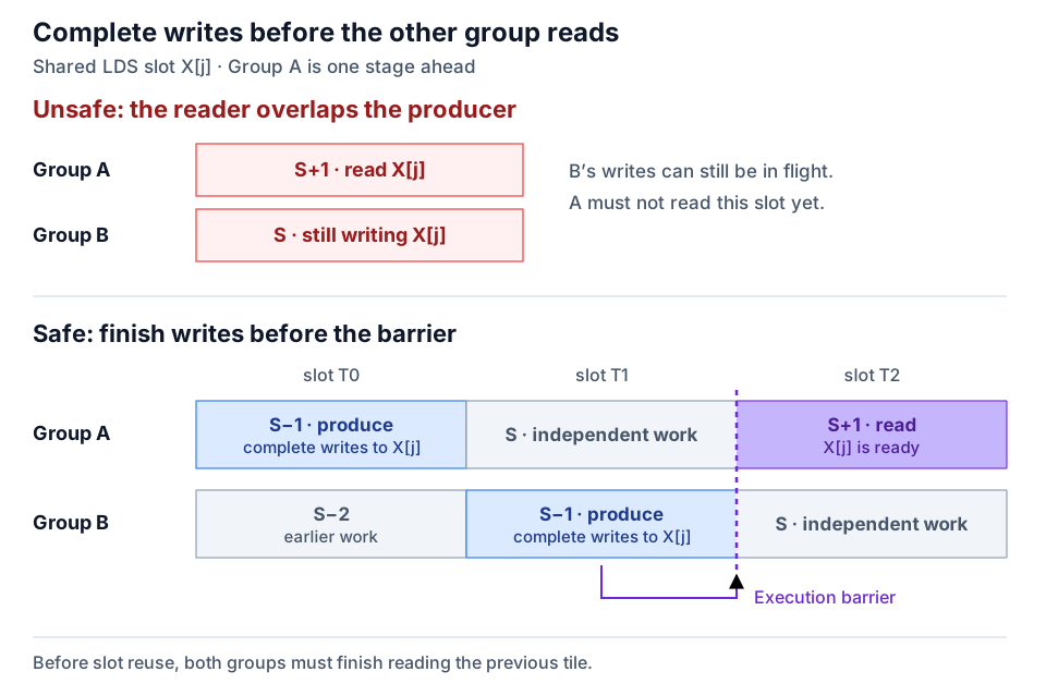
Figure 10. Completing shared writes before the leading group reads.#
If Group A reads an LDS slot in stage S+1 while Group B is still producing
it in stage S, a wait immediately before each group’s own read is too late.
The safe example completes each group’s producer work in S-1. By the time
Group B reaches the following rendezvous, its writes have completed, so Group
A can enter S+1 and safely read. For asynchronous copies, this requires an
explicit completion wait before arriving at the rendezvous.
This is why the earlier code places its wait before the MFMA stage that precedes the load. The same reasoning applies across iterations: reads of the current tile must finish before a later iteration refills the shared buffer.
Stage Size and Register Pressure#
Preserving overlap also requires enough registers and LDS for both wave groups. The reference schedule needs two resident waves per SIMD. Even when both waves remain resident, spilling adds memory traffic that can erase a performance gain.
Warp-pipelining separates operand production from consumption. Values loaded in a producer stage must remain in registers until a later matrix stage uses them. A larger producer stage prepares more values at once, increasing the number of live registers. Long, coarse stages therefore tend to worsen register pressure. Splitting the matrix consumer, such as a WMMA region, into smaller slices lets the corresponding producer work be split as well. Each producer then prepares fewer operands at a time, reducing register pressure and the risk of spilling. The slices must still provide enough matrix work to cover preparation without excessive barrier overhead.
Preparation time also depends on issuing the VALU instructions used for address calculation. If these instructions are delayed, the next operands may not be ready when the matrix stage needs them. Giving the preparation stage higher priority can help it issue that work sooner while the other group has matrix instructions in flight. Check the resulting schedule to see whether preparation finishes in time.
Choosing and Applying the Technique#
Warp-pipelining works alongside buffering and instruction scheduling. These techniques control different parts of the kernel:
Technique |
What it controls |
|---|---|
Double buffering, also called ping-pong buffering |
Where current and future tiles reside |
|
Which ready wave is favored for instruction issue |
Within-wave scheduling |
How one instruction stream interleaves matrix and memory work |
Warp-pipelining |
The relative stage progress of two wave groups |
Warp specialization |
Persistent task assignments to different wave groups |
Priority can encourage alternation, but does not synchronize a stage offset. Double buffering supplies storage, while warp-pipelining coordinates progress. The MI355X 4-wave comparison also shows that within-wave scheduling can achieve excellent overlap when its instruction sequence is well tuned.
For GEMM, start with a compute-bound shape whose trace shows recurring matrix-issue gaps around data preparation or synchronization. There must be enough matrix work to cover that preparation and enough resources for both wave groups. A memory-bandwidth-bound shape, a very short compute stage, or an unbalanced partition is less likely to benefit.
Profile a correct kernel and identify the gaps worth addressing.
Partition compute and preparation into stages, placing waits to protect cross-group dependencies.
Fill buffers in a prologue and drain remaining work in an epilogue.
Inspect IR or ISA for unexpected waits, fences, and instruction motion.
Check resident waves and spills separately.
Tune stage sizes using elapsed time, matrix efficiency, register use, and clock behavior.
Beyond GEMM: FlashAttention#
The same stage abstraction can express the inner loop of FlashAttention, which alternates QK and PV matrix products with online softmax and movement of the next key/value tiles. Softmax contributes VALU work that can overlap with matrix work from the other group.
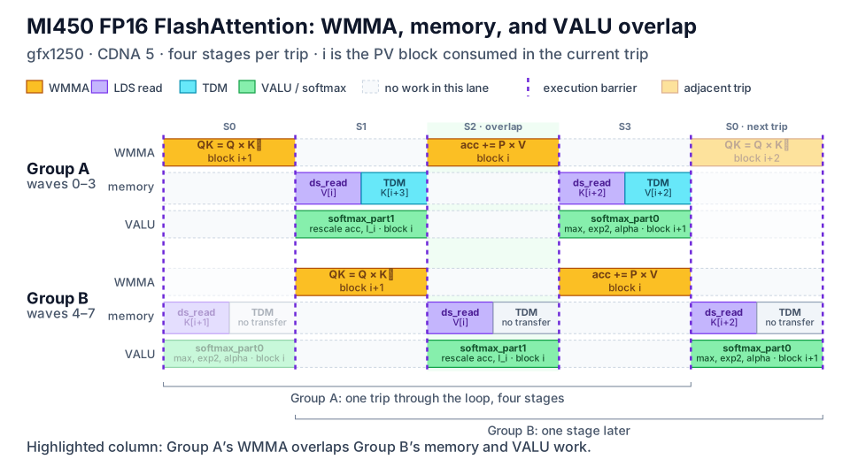
Figure 11. WMMA, memory, and softmax overlap in MI450 FlashAttention.#
In the illustrated loop, the QK stage computes scores for block i+1 while
the PV stage consumes probabilities for block i. The intervening stages
carry the two halves of online softmax and operand reads. Separate WMMA,
memory, and VALU lanes show how matrix work in one group overlaps both memory
and softmax work in the other. Only Group A performs the TDM data transfers.
The next trip advances i, so the next QK uses K[i+2], loaded during the
current trip. Stage annotations expose this schedule without requiring a
compiler pass to reconstruct it from an attention-specific loop shape. This is
a scheduling example. No attention performance measurements are reported here.
Bandwidth-bound decode shapes with little matrix work remain poor candidates
for this form of overlap.
Running the Kernels#
Use ROCm-enabled PyTorch, NumPy, and a recent source build of upstream Triton that includes the CDNA5 example below. Run each example on its matching GPU. The public kernels and compiler continue to evolve, so results can differ from the measurements above.
MI300X and MI350 Series#
Clone the Gluon tutorial repository on main:
git clone --branch main https://github.com/ROCm/gfx950-gluon-tutorials.git
cd gfx950-gluon-tutorials
For MI300X (gfx942), use the 8-wave kernel in
gfx942/inter_wave.
From the tutorial repository root:
python kernels/gemm/gfx942/bench.py -k inter_wave \
  --M 4096 --N 4864 --K 16448 --dtype bf16
For MI350/MI355X (gfx950), use
inter_wave/a16w16
on main. Its runner uses M=N=4096:
python kernels/gemm/inter_wave/a16w16/bench.py --K 8192 --dtype fp16
Both runners check correctness and report throughput. Either accepts
--dtype fp16 bf16 to run both data types.
MI450#
The CDNA5 warp-pipeline example is included with its helper modules in upstream Triton. From the Triton checkout root:
cd third_party/amd/python/examples/gluon

# BF16
python gemm_warp_pipeline_cdna5.py \
  --dtype bf16 -M 4096 -N 4096 -K 65536 \
  --input trig --benchmark \
  --warmup 20 --samples 1 --replays 20 --iters-per-graph 50

# MXFP8, two output buffers
python gemm_warp_pipeline_cdna5.py \
  --dtype mxfp8 -M 4096 -N 4096 -K 65536 \
  --mxfp8-tile 256x256x256 --mxfp8-cluster 4x4 \
  --mxfp8-output-buffers 2 \
  --input trig --benchmark \
  --warmup 20 --samples 1 --replays 20 --iters-per-graph 50

# MXFP4
python gemm_warp_pipeline_cdna5.py \
  --dtype mxfp4 -M 4096 -N 4096 -K 65536 \
  --input trig --benchmark \
  --warmup 20 --samples 1 --replays 20 --iters-per-graph 50
Add --check to validate the output before timing. Timing excludes input
generation, compilation, and correctness checking.
Summary#
In this blog, you learned how warp-pipelining makes relative wave progress part of the kernel’s schedule. Conditional barriers establish and close a one-stage offset, and stage rendezvous maintain it. Stage annotations let you express the compute and preparation regions while the compiler preserves their boundaries and accounts for memory dependencies across wave groups and iterations.
The reference GEMMs show how to adapt that schedule to VGPR-mediated copies on MI300X, direct asynchronous copies on MI350, and TDM/WMMA execution on MI450. Their operations and layouts differ, but the stage abstraction remains useful. The measured examples illustrate sustained matrix issue on suitable compute-bound shapes and performance comparable to carefully tuned kernels; the outcome still depends on the workload and target.
To apply the technique, start with the public kernel for your target, identify its compute and preparation stages, and examine the dependencies across both wave groups before adjusting stage boundaries. Use execution traces alongside throughput measurements to assess whether the resulting schedule sustains matrix issue on your workload. The linked Gluon tutorials and the companion MI450 LDS optimization post provide further examples of data movement and layout choices to explore.
Disclaimers#
Results apply to the measured MI300X, MI355X, and MI450 kernels and workloads described here. Performance varies with hardware configuration, ROCm and Triton versions, compiler settings, power and thermal state, and workload. Results may change as the software evolves. Measurements across GPU generations use different shapes and methods and should not be compared directly.
Third-party content is licensed to you directly by the third party that owns the content and is not licensed to you by AMD. ALL LINKED THIRD-PARTY CONTENT IS PROVIDED “AS IS” WITHOUT A WARRANTY OF ANY KIND. USE OF SUCH THIRD-PARTY CONTENT IS DONE AT YOUR SOLE DISCRETION AND UNDER NO CIRCUMSTANCES WILL AMD BE LIABLE TO YOU FOR ANY THIRD-PARTY CONTENT. YOU ASSUME ALL RISK AND ARE SOLELY RESPONSIBLE FOR ANY DAMAGES THAT MAY ARISE FROM YOUR USE OF THIRD-PARTY CONTENT.
The information presented in this document is for informational purposes only and may contain technical inaccuracies, omissions, and typographical errors. The information contained herein is subject to change and may be rendered inaccurate for many reasons, including but not limited to product and roadmap changes, component and motherboard version changes, new model and/or product releases, product differences between differing manufacturers, software changes, BIOS flashes, firmware upgrades, or the like. Any computer system has risks of security vulnerabilities that cannot be completely prevented or mitigated. AMD assumes no obligation to update or otherwise correct or revise this information. However, AMD reserves the right to revise this information and to make changes from time to time to the content hereof without obligation of AMD to notify any person of such revisions or changes. THIS INFORMATION IS PROVIDED “AS IS.” AMD MAKES NO REPRESENTATIONS OR WARRANTIES WITH RESPECT TO THE CONTENTS HEREOF AND ASSUMES NO RESPONSIBILITY FOR ANY INACCURACIES, ERRORS, OR OMISSIONS THAT MAY APPEAR IN THIS INFORMATION. AMD SPECIFICALLY DISCLAIMS ANY IMPLIED WARRANTIES OF NON-INFRINGEMENT, MERCHANTABILITY, OR FITNESS FOR ANY PARTICULAR PURPOSE. IN NO EVENT WILL AMD BE LIABLE TO ANY PERSON FOR ANY RELIANCE, DIRECT, INDIRECT, SPECIAL, OR OTHER CONSEQUENTIAL DAMAGES ARISING FROM THE USE OF ANY INFORMATION CONTAINED HEREIN, EVEN IF AMD IS EXPRESSLY ADVISED OF THE POSSIBILITY OF SUCH DAMAGES. AMD, the AMD Arrow logo, Instinct, ROCm, CDNA, and combinations thereof are trademarks of Advanced Micro Devices, Inc. Other product names used in this publication are for identification purposes only and may be trademarks of their respective companies. © 2026 Advanced Micro Devices, Inc. All rights reserved